
OWNER'S MANUAL
THE DAYTON WRIGHT ELECTROSTATIC
LOUDSPEAKER SYSTEM
Model XG-10 Mark 2
XIM-10 or XIM-11
![]()
DAYTON WRIGHT GROUP LTD.
![]()
Revised: MAY 19, 1982
CONTENTS
SALES INVOICE
3
INTRODUCTION
5
UNPACKING
6
POSITIONING
7
CONNECTING
8
DISCONNECTING
9
OPERATION
10
MAINTENENCE
14
SERVICE POLICY
16
WARRANTY
17
APPENDICES:
A. An Introduction to the
Electrostatic Speaker 20
B. Speaker Damage
25
C. Bias Setting & Discharge
28
D. System Instability
30
E. Information on prior models
31
F. Operation at high altitudes
33
G. Modifications
34
H. Use and connection of the XW-10 Subwoofer
35
I. Technical Information &
LIST OF ILLUSTRATIONS:
Figure 1. The XG-10 Mark 2 Speaker System 4
2. Front Panel & Controls 4
3. Speaker Placement (Horizontal) 7
4. Speaker Placement (Vertical) 8
5. Connectors 9
6. Circuit Board iX"I'M'1'1'i 11
7. Frequency Response 12
8. Impedence Response 13
9. Tear Repair 14
10. Schematic 38
WARNING: TO PREVENT POSSIBLE SHOCK HAZARD
THIS SYSTEM SHOULD NOT BE EXPOSED TO RAIN
OR MOISTURE.
PLEASE STAPLE
YOUR
SALES INVOICE
HERE
PLEASE BE SURE TO SAVE YOUR INVOICE
YOU WILL NEED IT TO VALIDATE YOUR WARRANTY
Fig.1 THE XG-10 Mark 2 LOUDSPEAKER SYSTEM
OPERATION OF THE SPEAKER SYSTEM
THIS ELECTROSTATIC LOUDSPEAKER SYSTEM IS NOTED FOR:
| HIGH POWER HANDLING CAPACITY
Lack of Transient Clipping even with High Power Amplifiers |
VERY LOW DISTORTION
With a revised diaphragm coating of much higher resistivity which results in improved constant-charge density operation. |
| INCREASED EFFICIENCY
Silicon-Stabilized Cell structure permits higher bias voltages with improved reliability. |
EXTENDED FREQUENCY RESPONSE
A New Tweeter and Optional Sub- Woofer extend the range, now16 Hz to over 30 kHz. |
| IMPROVED AMPLIFIER LOADING
Increased Minimum impedance allows more effective use of Power Amplifiers |
HIGHER SOUND PRESSURE LEVELS
Compatable with even the widest dynamic range Digital Recordings. |
| CHOICE OF INTERFACE MODULES
Either the XIM-10 or Professional XIM-1 1 maybe used with the units. |
DAYTON WRIGHT GROUP LIMITED, EXPERTS IN ELECTROSTATICS!
RESEARCH AND DEVELOPMENT RESULT IN SUPERIOR PERFORMANCE.
Many have commented about the quantum jump in the performance of the XG-10 Mk 2 Speakers. Twenty-five years of experience, combined with new facilities and a carefully planned program with the re-acquisition of the company by the founders of Dayton Wright Associates Limited. In preparation for this purchase, over a year of preliminary development was undertaken towards improvement of the fundamental design, and after the consummation of the purchase in June 1981, the development was intensified.
Through a comprehensive fault-analysis program, possible failure modes were studied, and existing designs modified or re-done as necessary to achieve much higher reliability. The goal was not simply to improve on existing designs, but to continue the technological advances that made the Wide Dynamic Range Electrostatic Loudspeaker possible in the first placel And this improvement in performance had to be accomplished at the same time as the reliability of the systems were increased.
Advances in materials Technology have also played their part, all plastic parts exposed to the strong electrostatic fields are now surface treated with a silicon resin to prevent carbon-tracking. The Cell diaphragm edges are now damped to minimize standing waves and lateral reflections using a process that was unavailable five years earlier.
The piezoceramic tweeter of former models has been replaced with a Electromagnetic Diaphragm Type unit having exceptionally linear response characteristics to well over 50 kHz. This was chosen over ribbon units as no current transformer was necessary for impedance matching while the design, which uses a polyamide diaphragm sandwiched between layers of damping material; is free from reasonances, and has exception ally low energy storage figures.
But improvements in the Transducers would not be worthwhile unless the Interface Modules could also be improved. Fortunately, the connector and cable standards established in 1976 allowed a system approach to be taken to the problem and a series of Interface Modules are anticipated any one of which can be used with the newXG-IOMk2Speakers. Twoof these models are no offered.
THE XIM-10 INTERFACE MODULE
This is a revision of the IM-10 Module with a new crossover system,
and level controls. It operates with a 9 Kv Negative Supply and permits
slightly higher output from the speaker than the IM-10. The tweeter
levels are now individually adjustable L-Pads.
THE XIM-11 INTERFACE MODULE
Designed for Professional Requirements, this Module operates with a
16 kV Positive Bias Supply for much higher efficiency. It takes advantage
of the very great improvement in carbon track resistance of the New Transducer
Cells. With internal Slide-Switch provision for 120/240 volt AC operation,
as well as for switched bypass of the E.S.L. networks, this unit is nevertheless
easy as only the essential controls are on the front panel.
SUBSTANTIAL IMPROVEMENT MADE IN REPRODUCTION
The XG-10 Mk 2 Electrostatic Speakers cannot be confused with earlier models on the basis of reproduction. The new units have much improved transient response, a smoother frequency response, lower distortion, and some subtle design revisions which have been made based on psycoacoustical tests; the result is not a subtle improvement, but a design which has stunned those Audiophiles who have heard the system. The transparency of the XG-10 Mk 2 Electrostatic is much higher than before with a transient cleanliness and impact that is absent on other Electrostatic Loudspeakers.
THE DAYTON WRIGHT DESIGN PERMITS VERY HIGH
SOUND PRESSURE LEVELS TO BE REACHED WITHOUT THE NEED FOR TRANSIENT-CLIPPING
PROTECTION CIRCUITS
Dayton-Wright pioneered the use of High Dielectric Strength gasses in the Electrostatic Loudspeaker. Eliminating the need for Stator Coatings which cause dynamic range compression effects in other Electrostatic designs, this Patented design allows transients to be reproduced without clipping. The Dynamic-Range of Digital Recordings can now be handled without any substantial increasing distortion from the Speaker, or non-linearities in the transfer function of the speaker.
WHY USE ELECTROSTATIC SPEAKERS AT ALL?
At the heart of the problem of creating the air motion we hear as sound, is the problem of what will be used to move the air itself. Something must respond in to the input signal, moving back and forth in an exact mechanical duplication of that signal, irrespective of variations in the air resistance with frequency, and problems created by its own physical structure. This 'piston' must have enough area so that it does not have to move an exessive distance to produce the large volume air displacements required at low frequencies, and yet to be light enough so that it can be moved with extreme rapidity to reproduce high frequencies.
It is not surprising that of all components in the Audio System, the Loudspeaker has created the greatest number of headaches for the designer. If he makes the cone or diaphragm rigid enough so that it will move as a single piston at low frequencies, it is probably going to be too heavy to be effective at high frequencies. If he makes it large enough to displace a reasonable volume of air with a reasonable displacment as required for low frequency reproduction, it is going to be far too directional at high frequencies.
And then there is the problem of converting the electrical signal to
mechanical motion, and making that conversion without distortion.
There will be compromises, there have to be compromises if he wishes to
drive his unit with a voice coil or coils. That is because the voice
coil drive makes its force available at the end of the cylinder supporting
the voice coil, while the air load is spread over the surface of the cone
assembly.
CONE TYPE SPEAKER
By dividing the audible frequency range into two or more bands, the
design problem is simplified, but not eliminated. But consider the
advantages of an electrostatic speaker design. The driving force
is not applied at one limited area, but uniformly over the suface of the
diaphragm that moves the air, in fact you can think of the driving force
being distributed over the surface of the diaphragm in just the same way
as the air load is distributed over the surface of the diaphragm.
There is therefore, no need to make the diaphragm rigid as there is no
need to transmit the driving force from the point where it applied, to
the area where it may be very thin and very light indeed. Unlike
a cone structure where much of the driving force is used to move the mass
of the cone, an electrostatic speaker uses most of the force to move the
air, as the diaphragm mass is negligible.
The electrostatic transducer consists of four parts, two perforated electrodes or Stators, a diaphragm (that bears a semiconductive coating) placed midway between them, and a supporting framework.
A high voltage Bias supply is used to place an electrical charge on
the diaphragm coating, and a step-up transformer places the signal on the
two stators in push-pull. Providing the charge stays constant, the
force acting on it will be exactly proportional to the audio voltage applied
to the fixed Stators, and providing the charge distribution over the diaphragm
is constant and remains constant, the force on all areas on the diaphragm
will be the same; this holds true no matter where the diaphragm lies between
the Stators.
ELECTROSTATIC SPEAKER
Page 4
INTRODUCTION
Thank you for purchasing this Dayton Wright Product. Each item
that we manufacture has been designed to deliver reliable service while
being a true State-of-the-Art unit. In order for you do derive the
maximum enjoyment from this product, we would ask you to read this manual
carefully. In it, we have tried to answer any questions which you
might have about the installation and operation of the Dayton Wright Electrostatic
Loudspeakers.
THE DAYTON WRIGHT ELECTROSTATIC LOUDSPEAKER
IS FUNDAMENTIALLY DIFFERENT FROM OTHER LOUDSPEAKER SYSTEMS, AND THEREFORE
IT IS WISE TO BE SURE THAT THESE INSTRUCTIONS ARE FOLLOWED. WHERE
THERE IS ANY DOUBT IN YOUR MIND AS TO THE PROPER INSTALLATION OR USE OF
THE SPEAKERS, PLEASE FEEL FREE TO CONTACT US AT THE FACTORY. WE WANT
TO MAKE SURE THAT YOU DERIVE THE GREATEST PLEASURE FROM THEIR USE, AND
THE BEST WAY FOR US TO DO THIS IS TO BE SURE THAT YOU HAVE BEEN ABLE TO
OPTIMIZE THEIR PLACEMENT, AND ARE USING THEM WITH THE CALIBRE OF ASSOCIATED
EQUIPMENT NEEDED.
GOOD LOUDSPEAKERS ARE LIKE WINDOWS, THE CLEANER THE GLASS, THE MORE
YOU CAN SEE. AND AS WINDOWS, THESE UNITS WILL NOT ONLY REVEAL DETAIL
IN YOUR RECORDINGS WHICH YOU PROBABLY HAVE NEVER HEARD BEFORE, BUT THEY
COULD SHOW UP MISADJUSTMENTS OF YOUR TONEARM, WEAR OF YOUR STYLII, OR HITHERTO
UNSUSPECTED DEFICENCIES IN YOUR ASSOCIATED EQUIPMENT.
BE SURE THAT THE UNIT ARE SET TO THE POWER LIKE VOLTAGE IN USE IN YOUR COUNTRY. MOST UNITS CAN BE SET FOR 110-120 VOLTS OR 220-240 VOLTS, AND SHOULD HAVE BEEN PRESET BY EITHER THE FACTORY OR BY THE DEALER.
UNPACKING
This is easiest if two people are available. Open the top of the
outer and inner speaker cartons, then tip the cartons over so
that the flaps are spread away from the opened top. Then slowly
slide the carton up and off the speaker.
The carton system used to pack the speakers was specifically designed
for this product, and is the result of over 10 years
of refinement. Because of the complexity, it is quite expensive.
Should you ever move, you would be advised to use the same cartons.
If for any reason you have to ship these speakers, the use of alternate
packing methods could void any damage claim you might have to make on the
basis of "Inadequate Packing". Your best protection is the use of
a carton system which has been proven in extensive use -
Now a new set of cartons can be obtained from the factory, but because
of their cost, a charge will be made for them. In addition, you may
well encounter shipping charges based on a minimum 100 pound rate even
though the cartons weigh less.
PLEASE SAVE THE CARTONS!
POSITIONING
Unlike previous generations of the Dayton Wright Electrostatic Loudspeakers,
the XG-10 Mk 2 system has been designed so that with respect to rear radiation,
room placement is no longer so critical as before.
Ideally, as shown in the Illustration, the speakers should be aligned
with the long axis of the Listening Room.
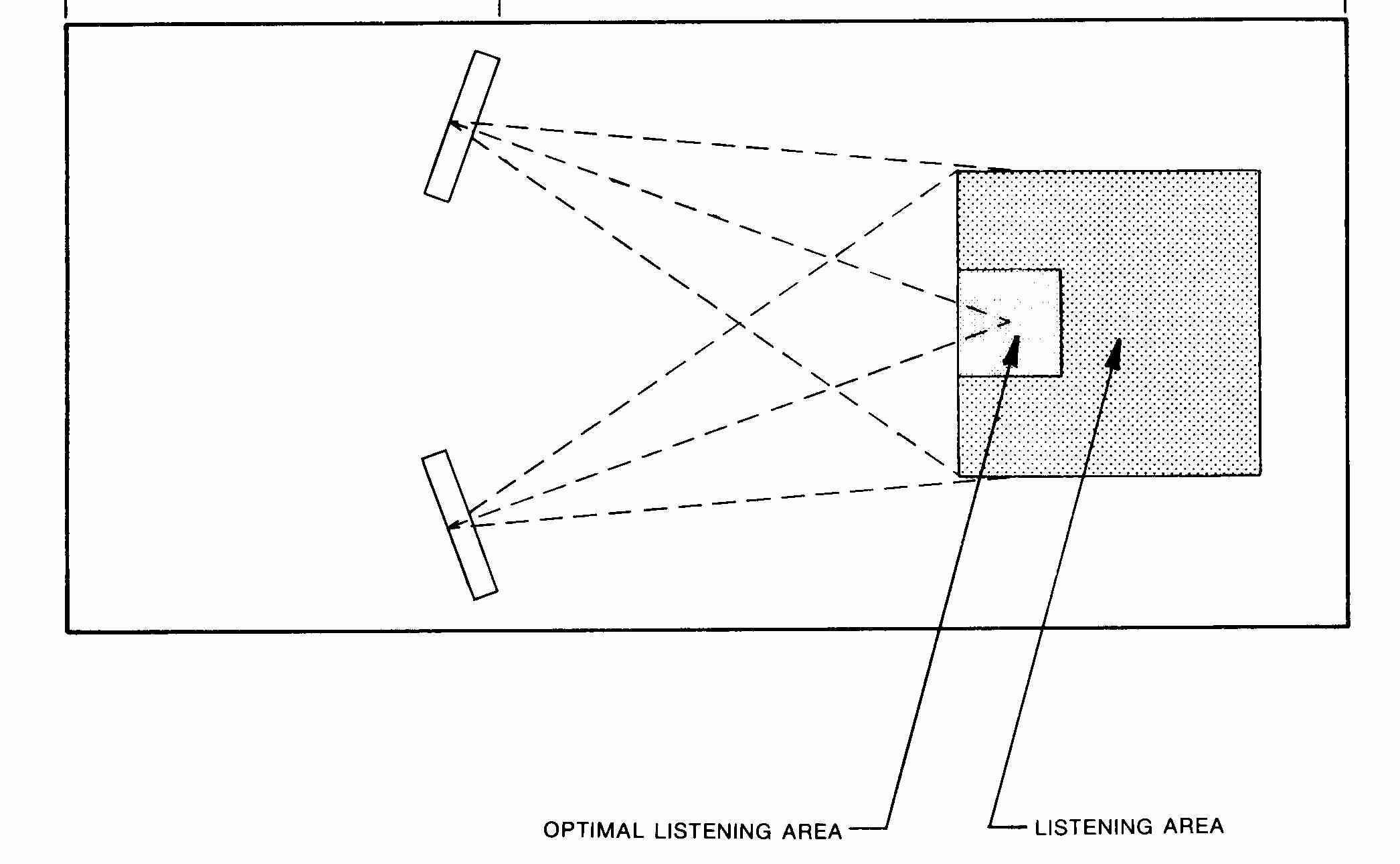
This will produce the best bass, and loudness of the reproduction.
However, the speakers can be used somewhat closer to the rear wall than
the 1/4 to 1/3 Room length previously specified, especially when using
the XW-10 Sub-Woofer System.
(see appendix)
Traverse positioning of the speaker within the Listening Room is also possible, although this will reduce Low Frequency output. Once again the use of the XW-10 pressure coupled Sub-Woofer will alleviate any Bass difficulties.
If the speaker must be used near a rear wall, it is important to position
it so that a volume is not defined behind the speaker that is not vented
on the top, and sides. By moving the speaker away from the side wall,
the speaker can be located closer to the back wall. In no case should
the speaker be located so that the average distance from its rear surface
back to the wall behind it be less than 2 feet (60 cm), unless the Sub-Woofer
is used when the minimum dimension can be dropped to 10 inches -
(25 cm).
i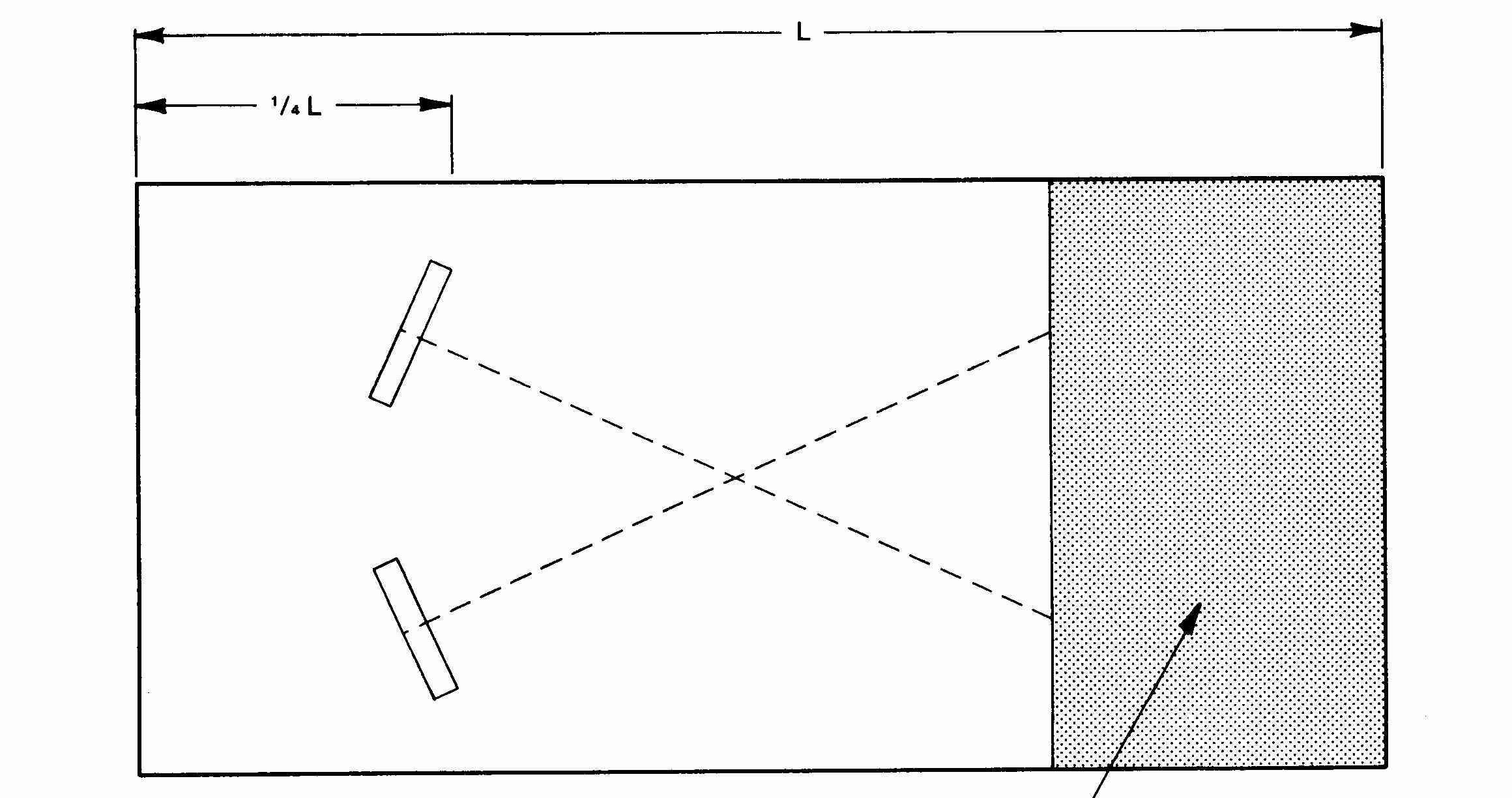
Fig-3 SPEAKER PLACEMENT - HORIZONTAL
The speaker should NOT be positioned so that its flat face is parallel to the wall behind it. A minimum angle of about 15 degrees is suggested.
If the speaker is to be used in front of French Windows or Glass Doors
there will be an increase in the reflected radiation at higher frequencies.
This may well require that drapes be used behind the speakers to avoid
an unusually bright upper-mid range. An adjustment is available which
will (to some extent) correct for this condition, but it should only be
attempted by a technician as it must be done within the XIM-10.
Speaker Separation.
This is a function of room size. In a small room there may only
be 3 feet (.9 meters) between the speakers. It is probably better
to reduce this if it means that 8 inches (40 cm) can be left between the
outer corner of each speaker and the sidewall. The limit of separation
is that where the center fusion drops out due to a disproportionate-amount
of reverberant sound; thus, if the room dimensions and decor dictate a
wide spacing (anything beyond that which places the speakers and the listener
(at the points of a equilateral triangle), some stereo fusion may . still
be possible if the area behind the speakers is not too 'dead' acoustically.
(Vertical Positioning & Angle)
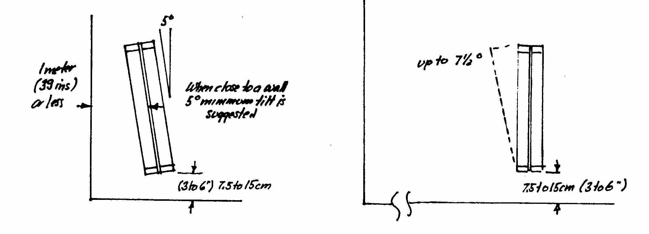
Fig.4 SPEAKER PLACEMENT-VERTICAL
The speakers may be mounted on any appropriate supports (an optional
stand system is available) from 2 inches (5 cm) to 8 inches (40 cm) from
the floor; tilting the speaker back about 5 degrees has been found helpfull
in lowering the principle resonance excited in some listening rooms, although
a vertical position is suggested if room , 'resonance is not a problem
and if the floor is not a highly reflective (stone, carpeted concrete slab,
tile, etc) material.
(was fig 1 in Leigh manual)
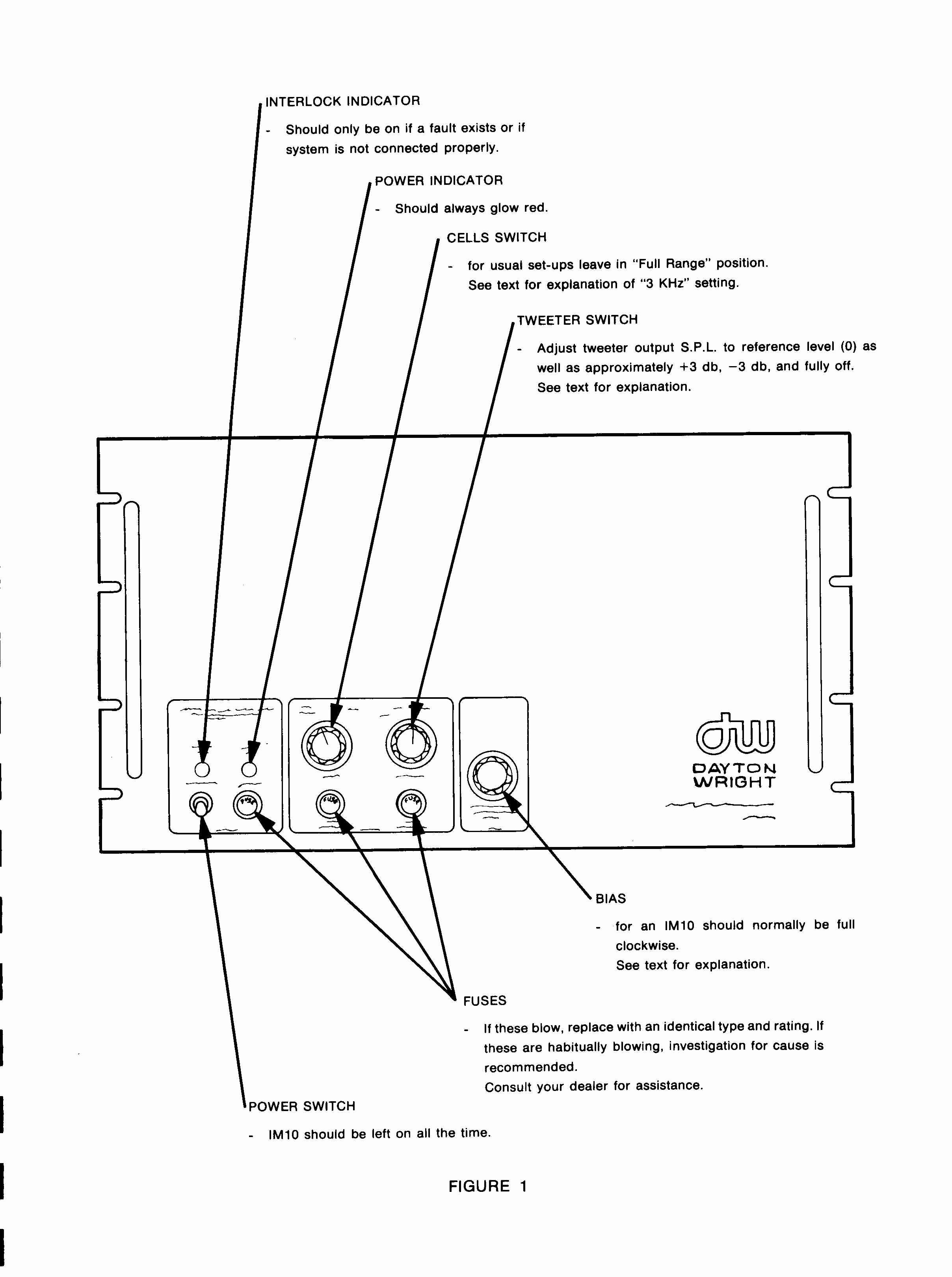
Fig..2 ILLUSTRATION OF XIM-10 FRONT PANEL
NOTE THAT THE 'CELL SWITCH', HAS BEEN
REPLACED BY ANOHER TWEETER LEVEL CONTROL
CONNECTING THE SYSTEM
1 Obviously you will have to place the XIM-10 in a position where its cables will reach both speakers. Attempts to cut the cable and/or to lengthen the cable are for-doomed to failure. Because of the special nature of the cable it is doubtful if even a stereo shop could make satisfactory splices or substitute other wire. The cable supplied on the XIM-10 was designed for the speaker and is of a special high-voltage low-loss type.
2. Connect the output terminals of your power amplifier to the input terminals of the XIM-10. As the XIM-10 produces no heat, the power amplifier may be placed on the top of the XIM-10; in order to reduce ground loops, it is advisable to make sure that the chassis or front plate of the Power Amplifier used, does not come in touch with the case or front plate of the XIM-10. A piece of corrugated cardboard placed under the Power Amplifier should be sufficient, but make sure that it does not block any cooling air vents on the Power Amplifier. For such an arrangement, short lengths of 12 gauge Flameseal or similar solid copper House wire will prove satisfactory.
We do not endorse the use of exotic wide bandwidth wire such as Litz-wire and its derivatives unless the appropriate termination network is mounted at the XIM-10 terminals. Wide Frequency passband wire, if not terminated, or improperly terminated, is prone to reflections which could cause your power amplifier to break into oscillation, damaging both the power amplifier as well as the loudspeaker! However, we have tested a number of the very heavy gauge speaker wires and have found that their use does improve the transparency of the speakers.
3. Laying the speakers on their sides, connect the XIM-10 unit
to the speakers using the cable and special connector provided..
Make sure that all of the connectors are securely in place.
4. Turn the bias control fully counter-clockwise.
5. Plug the XIM-10 into the wall power receptacle.
6. When the power switch is turned 'ON' the Red Neon Bulb should glow. If it doesn't, and/or if the amber interlock light comes on instead, either the auxiliary, or main fuse is blown or the panel interlock switch is open.
7. Slowly advance the bias potentiometer. You should be able to turn the control all the way counterclockwise without causing any discharge noise in the speaker.
8. Under normal conditions the speakers require about 36 hours to establish
proper operation. This is because some polarization effects take
place in the plastic parts, until this is completed there will be an unbalanced
field in some cells that will usually manifest itself as frequency or polar
pattern anomalies.
DISCONNECTION OF THE SYSTEM
When the Dayton Wright Electrostatics are disconnected there will still be a residual static charge on the internal parts of the system. This will dissipate in time, but in the period following unplugging of the cable connector from the speaker try to avoid touching any of the speaker connection pins. If this cannot be complied with, then we recommend the following procedure:
1. Turn off the XIM-10. Let the speakers sit for at least 10 minutes
before pulling out the cable connector from the speaker.
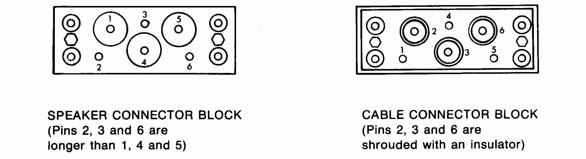
Fig-5 THE SPEAKER AND CABLE PINS
2. Using Insulated Handle pliers, short Speaker Connector Pin 1 to Pin 4, then short Pin 5 to Pin 4. A small spark discharge is normal. Do this on both speakers.
3. The Power Supply should be discharged by shorting the third wire ground contact on the Power Cord to socket 4 on the end of one of the speaker cable connectors. This only has to be done to one of the two cord sets. Either will suffice.
In Electrical terms, the force is proportional to the amount of charge, times the gradient, (rate-of-change with distance) of the electrical (signal) field. If the two Stators are a fixed distance apart, the gradient, will be exactly proportional to the voltage applied between the stators.
This sounds great. But a problem arises from the fact that air will only supporta gradient of under 70 kilovolts per inch before it breaks down! Thus there is a limit to how loud an air dielectric Electrostatic speaker can be made to play.
WHY USE DAYTON WRIGHT ELECTROSTATIC SPEAKERS?
Let us set aside the problem of sound pressure level for the time being, and consider design, construction, materials, and their effects on the sound of an Electrostatic Loudspeaker.
If the Transducer Cells are made too large, construction costs will be lower, but it will be difficult to achieve even distribution of high frequency sounds. If they are made too small, tooling costs can be cut, but the diaphragm may not be able to move far enough for good low frequency response. The supporting structure must be rigid, yet be free from self resonance, and the whole unit must be protected against things such as water, dust, and other contaminants.
The Dayton Wright Electrostatic Speaker has evolved over a period of 25 years from the first North American-built Full Range Electrostatic units. The generic precursor of the present design was the first Electrostatic Speaker to be designed specifically for low distortion and Sound Reinforcement use. It was felt that no speaker, whatever the cost, is going to satisfy the demanding Audiophile, unless it is capable of being played at sound pressure levels replicating the original. This includes transients which must not be compressed or clipped simplyto protect the speaker! It must be rugged, reliable, and have vanishingly low distortion at all frequencies, and at all volume levels.
The Dayton Wright Electrostatic Speakers have been designed to fill these requirements, using Transducer Cells which are specifically designed to optimize all parameters for the best possible performance. The Interface module similarity is a no-compromise unit. Where better results could be obtained from an electromagnetic diaphragm tweeter, one was fitted. And when experimentation proved that is was possible to set an extra octave of low-frequency response from a new technology sub-woofer, one was designed for use with the Electrostatic Speakers.
TRANSDUCER CELLS SPECIFICALLY DESIGNED FOR LOW DISTORTION AT ALL SOUND PRESSURE
The Dayton Wright Electrostatic uses ten identical individually built wide-range Transducers Cells robustly mounted tangent to the surfact of an oblate spheroid. The assembly is housed in a heavy gauge
steel enclosure forming a gas tight channel frame; which is covered, front and rear, with polyester film forming a hermetically sealed enclosure; filled at atmospheric pressure with an inert high dieletric strength gas.
Each Transducer Cell consists of two high purity polystyrene frames
to which the perforated template Stator Electrode is riveted at four places.
These acoustically damped stators lie on eith side of a polyester Diaphragm
cemented to and clamped
between the frames. The diaphragm has a semiconductive fluorocarbon
based coating cured to its surface in a carefully applied pattern.
The polystyrene frames, which have an exceptionally high resistivity,
are surfaced with a Silicon resin material which exhibits extremely good
track resistance.
The edges of the polyester diaphragm are coated with a damping material
to prevent reflections from the edge of the frame which would otherwise
form a compliance discontinuity.
The Stators have been designed to produce very smooth electric gradients
within the transducer even at high Sound Pressure Levels, and the entire
structure is non-resonant.
The result is a Transducer Cell which has exceptionally low bias leakage
and which, therefore, is able to use an ultra-high resistance coating permitting
constant charge density operation and (low distortion) even at Low Frequencies.
LARGE CORE TRANSFORMERS REDUCE
DISTORTION

But it is not enough to have Low Distortion in the Transducer Cell. Dayton Wright pioneered low distortion matching transformers as well. These use very heavy weight large cross sectional cores, and are insulated for safe, reliable, saturation-free operation at very high Sound Pressure Levels. These do not produce loading anomalies at low frequencies, and even at D.C. the system is designed to present a 10 ohm load to the Power Amplifier!
While our customers have occasionally complained about the weight of our Interface Modules, they have always been built with the anticipation of very wide dynamic range sound source materials. While this has increased their cost, it has prevented obsolescence, and even now older units can be updated at the factory.
Housed in steel relay rack comparable cases, both Interface Modules have handles on the rear as well as the front to assist with their movement. They come with two fifteen foot speaker connection cables.
VERY HIGH SOUND PRESSURE LEVELS POSSIBLE ONLY WITH PATENTED DAYTON WRIGHT DESIGN!
For the reproduced sound to be accurate and sound accurate the dynamics
of the original recording must be reproduced without clipping of transients.
To be usable in a real world, the speaker must be capable of operating
at levels much lower than the source material, as well as at comparable
levels. All of this calls for wide dynamic range and clipping-free
headroom beyond even the capabilities of many cone speaker systems.
Some Electrostatic Speakers manufacturers have found it necessary to
install various forms of protection circuitry to prevent damage of their
Transducers. These circuits 'clip' or compress the input signal at
some point so that overvoltage does not cause an arc within the speaker.
And other Electrostatic Speaker manufcturers use insulation on their
stators both for arc protection and so that they can achieve a usable level
of efficiency.
SECTION THRO' INSULATED-ELECTRODE ELECTRSTATIC
SPEAKER
NOT USED IN DAYTON-WRIGHT ELECTROSTATIC
Both approaches have validity, but when their use restricts the dynamic range of the speaker during normal operation, then they are not satisfactory.
If a coating is employed on the Stator, as shown, it does provide Arc Protection. Once the gradient between the sufact of the insulated electrodes is high enough to cause dielectric breakdown of the air, the increased current flow causes a drop in voltage across the insulation itself, quenching any arc before the current flow becomes dangerous. But the force on the diaphragm is proportional to the gradient of the electrical field in the gap; therefore, if we place an absolute limit on that field gradient, we place an absolute limit on the force that can be applied to the diaphragm as well.
The Dayton Wright Electrostatic Speaker uses a physiogically and physically inert gas in the Transducer. The gas selected has a dielectric breakdown voltage about four times that of air. The result is that there is the potential to use4timesthebias voltage of an air-gap-electrostatic, as well as4timesthe signal voltage as well. As 4 times the bias would result in a 12 dB increase in Sound Pressure Level, and 4
times the Signal Voltage would also result in a 12 dB increase in SPL, this could permit a 24 dB increase in the output of the speaker before any protection measures became necessary! It is therefore highly unlikely that the clipping level of the Transducer Cells in the Dayton Wright Electrostatic Speaker will ever be reached in normal service.
LOW GRADIENTS AND LOW ACOUSTIC GLARE
When you listen to music in a concert hall, in a night club, or even in a church, the rate of change of level with increasing distance is quite small. If you move back say ten feet, the level will drop only by a small amount. This is because the sound comes from a large area. With a typical Home Stereo system this is not true. Because the sound comes from small area sources, it drops in level rather quickly. This results in what we term, "Acoustic Glare". It is analogous to the glare from two small bright lights when compared with the lack of glare from a distributed source. The latter is much easier to live with.
Now this is not to say that we consider indirect sound sourcing as satisfactory as indirect lighting. While bouncing the sound off the wall of a room may produce a large apparent source, the multiple-path lengths between the Speaker and the Listener will hopelessly blur all detail.
Because of the large radiating area (almost a square meter) of the Dayton Wright Electrostatic Speaker, the units are remarkably free of acoustic glare. Yet the small area super-tweeter provides the accurate source for precise stereo fusion of instruments such as cymbals.
THE DAYTON WRIGHT SUBWOOFER SYSTEM
Because many rooms do not permit a Velocity-Coupled (Dipole) transducer to generate really low frequencies we have developed an optional sub woofer. While many have tried this before, there usually was a major change in sound character between the Electrostatic Speaker and the Subwoofer, partially as a result of the crossover, and partially as a result of the respective distortion spectrum differences.
The Dayton Wright Electrostatic Speaker has been redesigned to have a smooth low-frequency roll-off without the rise in distortion common to cone speaker systems. The Sub-Woofer system has an internal crossover that is complementary to this roll off characteristic. Together, they produce a seamless response down to below the level of human hearing that is remarkably free from the harmonic distortions that make other hybrid systems sound false.
The unit is housed in a single small cabinet with two independent woofers. These are high gyratory-moment drivers with a flat front construction, and useg highly-linear inert gas in bags within the robust enclosure to achieve very low distortion. The gas has a speed of sound one third that of air, and for distortion purposes, thus has a volume equivalence of some 27 times that of air. Because several sealed bags are used, the enclosure does not appear to be a parallel piped, and it is therefore quite aperiodic.
Because the Electrostatic Speaker has a very high input impedance at low frequencies, it does not really load down the Power Amplifier. And as there is no distortion rise below rolloff (rolloff is due to cancellation, not to mass-reactance effects), no distortion-introducing crossover is needed before the Electrostatic Speaker's input!
ASSOCIATED EQUIPMENT
Every effort has been made to make the XG-10 Mk2 Speaker compatable with Power Amplifiers. But as the window is opened, more dirt may blow in, so it is with an ideal speaker. It is ruthlessly revealling, on many records it is possible to hear the ambience change as microphones are cut in or out. Poor microphone technique, phasing anomalies, all are quite evident; as are mistracking and phono-cartridge deficencies.
But at the same time, there is much less unconcious mental processing
necessary on the part of the Iistener to achieve realism in the stereo
presentation; we feel that this leaves more capacity for perception and
enjoyment. Thus the speaker is relaxing to listen to, there need
be no listening fatique if the system is properly set-up.
OPERATION OF THE SPEAKER SYSTEM
BIAS SUPPLY AND ADJUSTMENT
1. The Bias supply control will normally operate at the full clockwise position without any discharge being heard from the speaker. Occasionally, if the power line voltage is high, or the humidity is especially high it may be necessary to turn the Bias Supply control down by rotating it clockwise slowly until the discharge noise stops.
2. The XIM-10 unit is usually left turned on all the time, the current drain from the power line is minimal once the speakers have 'charged up'. If you plan to leave the speakers unattended and unused for several weeks, the supply can be shut off, but a short 'recharging' period will be necessary. If this cannot be tolerated, the bias control should be rotated counterclockwise about 60 degrees to reduce the applied voltage. Remember to turn it to its previous setting before using the speakers.
3. Unlike the Leigh Industries version of the XG-10, we have removed the external switch which permitted the electrostatic units to operate as Full Range Units. Instead we have installed separate High Frequency Controls for each speaker. In our experience it is not unusual to find that a room is not completely symmetrical in its high frequency response. By using separate continuously adjustable controls we have permitted come compensation to be made for asymmetry as well as for the general High Frequency characteristics of the listening room. Normal setting of the controls ranges from 11:00 to 12:30 o'clock for the pointer position.
SPECIAL SECTION FOR XIM-11 OWNERS
For Owners having the XIM-11 unit (professional version of the XIM-10) -there are certain additional controls available inside the case of the unit. (See Illustration of XIM-11 Circuit Board). A person having Professional Audio experience should only set these.
A/ Line Voltage Set Switch.
This slide switch sets the line voltage either in the 110 to 125 volt or
the 220 to 245 volt range. Use on the lower range in countries having
220 to 245 volt service will damage the High Voltage Power Supply and void
the warranty.
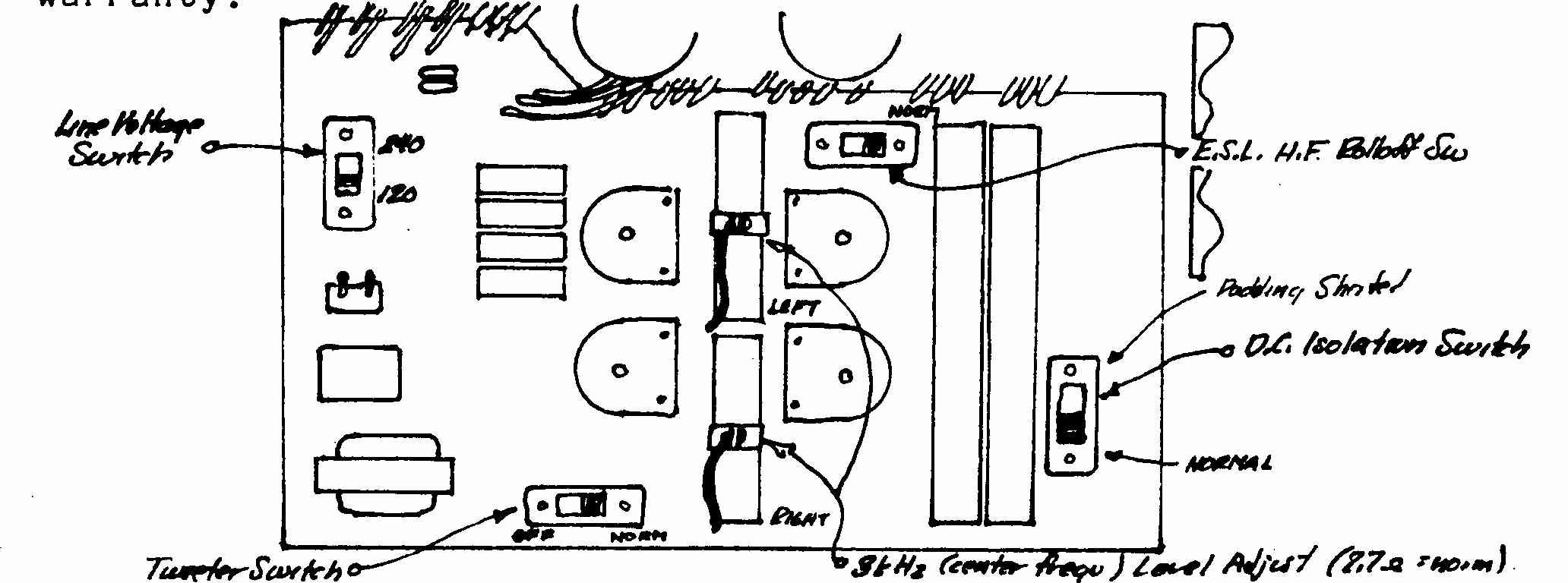
THE XIM-11 CIRCUIT BOARD CONNECTIONS
Fig 6 - THE XIM-11 CIRCUIT BOARD
This is much simpler than the Leigh board - that was a copy
of the Dayton
Wright Associates Ltd., experimental & circuit test board.
Fig
6A The Circuit Board used in the XIM-11/TPA
This incorporated the two tweeter amplifiers
and the crossover as well at the protection circuits
for the leaf tweeters.
B/ D.C. Isolation Switch. This slide switch, in the normal position inserts a network (consisting of a 750 uF Non-Polarized capacitor in parallel with a 8 ohm 100 watt resistor) in series with the primary of the Electrostatic Speaker Step Up Transformer. This has the effect of insuring that at Very Low Frequencies, or at D.C., the impedance of the speakers is at least 8 ohms as some D.C. coupled Power Amplifiers go into an 'Offset Protection Model if they see a D.C. resistance on their output terminals of much less then 4 ohms. In the other position, this network is bypassed.
C/ Tweeter Switch. This disconnects not only the tweeter, but its crossover network from the Input Connections of the XIM-11.
D/ E.S.L. H.F.Rolloff Network Switch. This switch bypasses the network which rolls off the H.F. response on the Electrostatic section of the Speaker. Its use at other than the Normal Position will also result in a substantial drop in the Minimum Electrical Impedance of the Speaker System, to a level that many power amplifiers may be unable to tolerate.
E/ 3000 Hz Center Frequency Control. When the speaker leaves the factory this slider is set so that the frequency band from about 1200 Hz to the tweeter crossover frequency is flat with respect to the range below 1200 Hz. Tilting back the speaker may require that this setting be reduced slightly as per the markings on the board. The slide setting can also be used, within limits, to adjust the speaker to the listening room. This should be done only by properly qualified personnel using a 1/3rd octave spectrum analyzer with a pink noise source.
CAUTION
THE XIM-11 HAS AN INTERLOCK SWITCH MOUNTED SO AS TO SHUT OFF THE UNIT WHEN THE OUTER (BLACK) FRONT PANEL IS REMOVED. AS A.C. AT POWER LINE VOLTAGES IS PRESENT (AS MARKED) ON THE LEFT SIDE OF THE P.C. BOARD, THE SWITCH SHOULD BE DISABLED, FOR INTERNAL ADJUSTMENTS ONLY BY PROFESSIONALLY QUALIFIED PERSONNEL. ALL INTERNAL ADJUSTMENTS ARE MADE AT THE RISK OF THE OWNER. NORMALLY WE RECOMMEND THAT THE XIM-11 (AND XIM-10) BE UNPLUGGED FROM THE POWER RECEPTACLE BEFORE THE CASE IS OPENED.
NOTICE
DAMAGE CAUSED TO THE SPEAKER THROUGH USE OF ANY OF THE INTERNAL SWITCHES SET AT OTHER THAN THE NORMAL POSITION IS NOT COVERED BY WARRANTY. IN THIS WE FOLLOW THE PREVIOUS POLICY AS REGARDS TO FIELD MODIFICATIONS. FIELD MODIFICATIONS WILL VOID THE WARRANTY AUTOMATICALLY. THE ADJUSTMENTS DO ALLOW THE SPEAKER TO BE USED WITH SOME OF THE NON-HARD-WIRED FIELD SYSTEMS, WHILE THE WARRANTY IS NOT VOIDED BY RE-SETTING ANY OF THE SWITCHES, MISUSE, OR SYSTEM MALFUNCTION CAUSED BY ANY OF THESE SETTINGS, WHICH CAUSES DAMAGE TO THE SPEAKERS WILL NOT BE COVERED BY THE WARRANTY.
4. The XG-10 Mk II Electrostatic Loudspeaker System is somewhat
unique in the amount of information it reveals not only about the source
material but about other components in the system. It is vitally
important that the tone-arm and cartridge be properly set up, for example.
If a moving-coil cartridge is used, be sure that the output of the pre-preamplifier
is not so great as to cause overload of the phono-preamplifier on peaks
as this will be immediately audible as strident high frequency response.
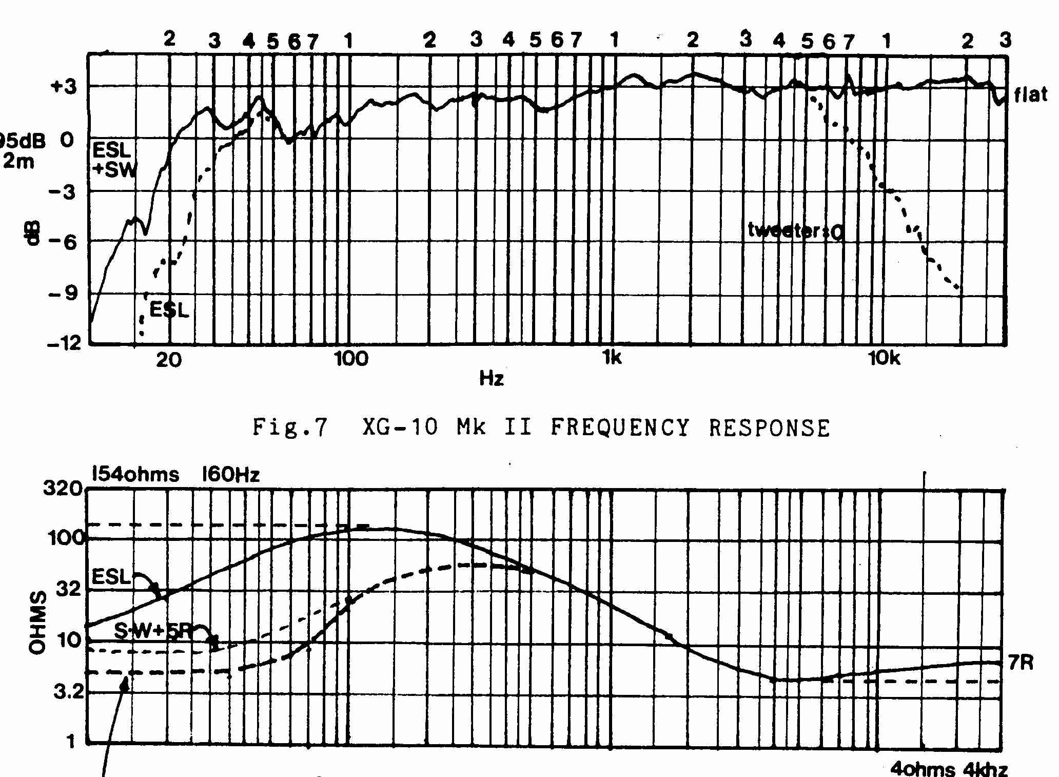
Fig-7 XG-10 Mk II FREQUENCY & IMEDANCE RESPONSE
4ohms 4khz with SubWoofer
It is our conjecture that the human brain processes all audio information in an attempt to fit it into a framework that is familiar. The more natural the sound is to begin with, and the lower the distortion, the less of the available mental processing capacity is tied up with this psycoacoustic normalization, and the more is available for perceptual discrimination of detail. In addition, this makes the sound quality less irritating, and results in a more relaxing listening experience. No one enjoys driving against the glare of the sun, and so it is with good audio; acoustic glare effects while dramatic, are exhausting unless they are used sparingly as deliberate dramatic effects.
Because
of the lack of Acoustic Glare from the Speaker, the listener may well find
that the playback level has been set much higher than normal, and this
could cause Power Amplifier overload! One secret to achieving convincing
acoustic illusions is to have the playback level set to that level consistent
with the type of music as well as the type of acoustic ambience in which
the recording was produced. If contradictory level or balance information
is present, proper stereo depth and fusion may not be possible. We
have found that, in general, the more accurate the speaker system, the
more care must be exercised in its use to achieve even acceptable results,
let alone attain the potentials possible with that system!
MAINTENANCE:
Aside from occasional inspection with the Power Amplifier turned off, to be sure that there is no Bias Discharge Noise; the speakers themselves should require no maintenance save waxing and/or oiling of the wood trim. Owners sometimes express concern over the possibility of gas leaks from the sealed speakers; however prior to their shipment from the factory, the speakers are inspected for possible leakages with equipment that can detect as small a leak as 2 oz. per year. As the gas is not pressurized within the cabinet, there is little to force a leak save the weight of the gas itself. The cabinets are both welded and sealed very carefully.
The gas that fills the cabinet is SF6 (sulfer hexaflouride) - an inert 'ideal' gas that is a much better insulator than air. If it needs topping-up because of a tear (typically most tears are caused by cats leaping up to the top of the speaker. The damage is caused by their rear claws piercing the front diaphragm of the speaker. SF6 can be purchased fom most lab-supply companies as lab demostration-size cylinders (ranging from 2 to 5 Lbs.).
DO NOT ATTEMPT TO USE PROPANE AS IT IS EXPLOSIVE!
PERFLOUROPROPANE CAN BE USED ONLY FOR TOPPING-UP AFTER A MINOR TEAR.
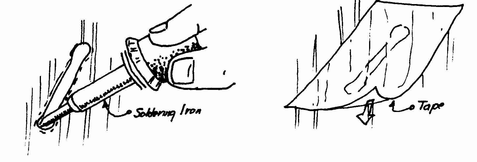
Fig.9 REPAIR OF TEAR
Obviously, should either the front or rear membranes sealing the enclosure become damaged, a leak will occur. In this case service is required. If the damage is noticed as soon as it happens lay the speaker with the undamaged face down. As the grill cloth is usually damaged as well, cut the cloth in a line parallel to the weave to expose the tear. Use the tip of a hot soldering iron or the heated end of a nail (heated on the burner of a kitchen range) to 'stop-off' the ends of the tears, melting a hole in the sealing film there. The thickened edge so formed will prevent the tear from spreading. (See Illustration)
Then preferentially use at least a 2 inch (5 cm.) wide Mylar (plastic) (available from 3M) tape to cover the tear; making sure that the edges of the tape do not have wrinkles which would allow the gas to leak out. Any wrinkles in the underlying sealing film may be shrunk out using hot air from a hair dryer.
Where the Mylar has to be cut to replace a bias resistor, a much wider Mylar tape has to be employed.
Once the tear is repaired, the seal band may be cut, and the four allen head screws holding the wood trim removed. The cloth sleeve may be lifted off and(the cut sewn up. (See Appendix B)
When
you want to top-up your speakers, you have to have enough SF6 on hand to
at least achieve a
40-60% fill. The amount you will need depends
on any diapragm damage - was the damage at the top
(less SF6) or at the bottom (a large lecture
bottle) as well as how long the diapragm was leaking.
At
the plant, we used 1.1 lbs per speaker - this allowed for some spillage.
Remember, SF6 contracts as it
gets cold - and that's why we took our time in
filling ESL's. Otherwise, when the SF6 gets to room
temperature the actual volume can double! Look
for diagraphm bulging when filled and prematurely
sealed. By filling each speakers in three
stages (slowly), and pausing for a half-hour after each stage, the
SF6 will have a chance to expand as it acheives
room temperature.
This will minimize the SF6 wastage.
Replacement of front or rear HS mylar.
We received a request from a customer about replacing the Mylar.
We advised him to contact Bostik. Here is his reply:
"The Bostik adhesives that I received were:
AQUAGRIP 8900
AQUAGRIP 8769
both are thin film elastomers that are water based and do not require a catalyst or additive."
The next stage is to remove the cabinet tops and bases by first removing
the fiberglas-reinforced black band
that runs around the cabinet. the ends are usually hidden underneath
the serial number plate on the bottom of the speaker. Save the plate! The
band is held in place by the use of a pair of wire hooks that look like
the type of wooden clothspin springs. Try not to damage them.
The wooden caps are secured by four allen-head screws for each cap. With both removed, carefully lift off the grillcloth frame being cautious not to tear the Mylar. This will expose the steel-frame'd speaker.
We advised him to go out an buy several polyethylene drywall tools about 4" wide. Then my only advice is that:
1) Try and mask-off
the exposed cells with newspaper and masking tape,
2) Use a small orbital
sander to remove ALL of the old Bostik stuff from the steel frame!,
3) Use a small vacuum
cleaner to remove all the crud - then place the speaker open-side
down and slap the diaphragm
several times to dislodge any crud remaining,
4) Reduce the room
temperature below 66 degrees so that the Bostik won't cure so fast,
5) Stop and rest,
6) Remember, two people
are needed to handle the mylar,
7) Then apply a reasonably
thin layer of the NEW water-based adhesive to the frame by using
a
plastic drywall tool, (aim
for about 1/32"thickness).
8) Use another plastic
tool to burnish the mylar flat - too thick a layer will cause bubbles
forming because of moisture
entrapment.
9) Wait 24 hours at
75+ for the stuff to cure.
10) Apply a 3" wide layer
of Mylar tape over the edge of the speaker and another later so
that it is about 3/4" to
1" past the diapragm edge.
Use a soldering iron to melt a 1/2" hole in the upper corner of the Mylar. This is to allow the air to ecape when the SF6 is slowly repaced by the use of the tire-valve beside the loudspeaker connector.
It will require about 1.1 pounds of SF6 per speaker. The SF6 gas may detected by the use of a glass cup with a small birthday candle candle waxed to the bottom. The cup is placed under the escape hole after the candle is lit. When the SF6 fills the cup the cande will be extinguished. SF6 won't support combustion!
Use Mylar tape to path the hole. A thin bead of Goodyear Pliobond (tm) on the edge of the Mylar will prevent peeling.
Replace the grill-cloth sleeve. Replace both caps usind the Allen-head screws. Replace the band.
This will be left as an excercize for the reader.
Seriously, several different tupes or bands were used. We can supply
both the band the 'gismo's that were used. Call us at 1-905-508-7500
When replacing the fabric on these speakers we advise customers NOT to use the old jute that was used for many years. It was origionally used as it had a "hard" fiber thad didn't absorb high frequenciencys. We swithed to a "Roman bridge" knit grill cloth as it was easy to stretch. We first had to stretch this fabric around the "frame" of the entire cabinet' then we stapled it into the entire lenght of the groove on one side of the frame.. After that we would work around the speaker frame plaing a staple on the top center and the bottom center of the frame. Then we would divide the speaker frame into equal parts and would place a staple in the center of each and would alternate both on the top and bottom as well as both ways outward from these new center staples until the frame was covered with tight fabric.
Then we had to make the frabric stick to the grooves. To do this, we made five foots lengths of three inch by eleven sixteenths of an inch thick and used light gauge polyethylene to prevent any glue from sticking to these clamping strips. The glue was only carpenter's glue applied sparingly onto the surface of the fabric. Then we used a pair of clamps just outside the frame, and left the clamps in place for about two hours. If the carpenter's glue was applied properly (Not to excess), the fabric would stick to the botto of the groove.
We would also use a piece of two inch wide corrogated cardboars at both the inside of both tops and bottoms of the frames, to prevent crud from tearing the now tightly stretched Mylar (TM) when the frame was slid over the steel inner cabinet.
On special orders we would use a tightly woven stainless-steel mesh (this high-denier stainless-steel mesh is used to produce durable silk screens designed for professional use. It is available in a finer mesh than is used in womans Nylon stockings.
Apart
from attempting to "Cat Proof" these ESL's we were concerned about the
possible physiological effects of the electrotsatic fields
NOTICE:
IT IS IMPORTANT THAT YOU NOTIFY THE FACTORY
OF YOUR ACTIONS AS SOON AS POSSIBLE
SO THAT THE RECORDS FOR YOUR SPEAKER MAY BE
UPDATED.
IF THIS IS DONE, AND LATER EXAMINATION SHOWS
US THAT ANY OTHER FAILURE WAS NOT DUE
TO AN EXCESSIVE LOSS OF GAS THROUGH THERE
BEING A LONG DELAY BETWEEN THE DAMAGE
AND THE REPAIR, WE WILL HONOUR THE WARRANTY
ON THAT SPEAKER.
THE EFFECTIVENESS OF THIS TYPE OF REPAIR WILL
DEPEND UPON HOW SOON ACTION WAS TAKEN,
AFTER THE PUNCTURE HAPPENED!
A LARGE TEAR AT THE BOTTOM WILL DUMP THE GAS
WITHIN 10 MINUTES.
ON THE OTHERHAND, A SMALL TEAR AT THE TOP
WILL REQUIRE PERHAPS,
24 HOURS TO CAUSE A SIGNIFICANT GAS LOSS.
THUS IT MAY NOT BE WORTHWHILE ATTEMPTING THE
FIELD REPAIR!
If on inspection, there is no tear but simply a 'dent' in the plastic film, this may be shrunk out by using the hot air from a hair dryer. Proceed with caution, start off with the dryer nozzle about 20 inches (50 cm.) from the plastic film and wait about 30 seconds to see if the shrinking starts. If it does not, move the nozzle some 2 inches (5cm.) closer and repeat the sequence until shrinking takes place. You should not be able to see any evidence of damage on the diaphragm once this is done.
THE USUAL CAUSE FOR DIAPHRAGM DAMAGE IS CATS (AND SOMETIMES DOGS) SCRATCHING THE GRILL CLOTH. IN SOME CASES THERE WILL BE NO ACTUAL TEARING OF THE CLOTH. IF YOU HAVE A PET THAT MIGHT DO THIS WE WOULD SUGGEST THAT YOU SPRAY THE GRILL FABRIC, BOTH FRONT AND REAR, WITH ONE OF THE PROPRIETORY REPELLANTS.
IF YOU DESIRE MORE PROTECTION THAN THIS, WE CAN SUPPLY GRILL SLEEVES THAT HAVE BEEN REINFORCED WITH A SCREEN-WIRE MESH, AT EXTRA COST. THESE INCORPORATE A VERY FINE MESH STIINLESS STEEL CLOTH OVER A THIN LAYER OF FABRIC WITH A COARSER SCREEN CLOTH BEHIND. THE STAINLESS STEEL CLOTH IS HIDDEN BEHIND THE USUAL GRILL CLOTH. ITS MESH IS SO FINE THAT A CATIS CLAWS WILL HAVE DIFFICULTY PENETRATING. IT SHOULD BE ORDERED THROUGH YOUR DEALER, WHO WILL HAVE TO INSTALL THE SLEEVES ON YOUR SPEAKER. WE RECCOMEND THAT HERE ALSO YOU SPRAY THE FRONT AND REAR OF THE GRILLIS WITH ONE OF THE PROPRIETORY REPELLANTS RENEWING IT AS NECESSARY.
1. It has been our experience that some owners of Dayton Wright Loudspeakers who live in coastal areas have experienced corrosion problems with metal parts, particularly with the pins on the speakers. While it is never good policy to let rain strike the back of the speaker, this is especially true in coastal areas as the salt in the air, and will be carried down in the fabric to the bottom of the speaker where it and the humidity WILL cause corrosion. If this possibility exists or if you are in a seashore area we would suggest that you coat the plastic parts of the connector with a Silicone Grease such as General Cement (GC Electronics) type Z5, Catalogue #568-S which you should bm able to obtain from the nearest electronics supply house. TV installers use this material to coat plastic twin lead to stop moisture and ice-buildup so it is a fairly common material.
2. DO NOT ALLOW DISCHARGE TO OCCUR & CONTINUE. (See Appendix. B)
IT IS VERY OBVIOUS, ON INSPECTION OF THE CELLS, IF AN OWNER HAS DISREGARDED THIS INSTRUCTION AND THE DAMAGE WILL BE CLASSIFIED AS MISUSE OF THE SPEAKER, AND THEREFORE, NOT UNDER WARRANTY.
3. In some cities where there is a high Sulfur Dioxide content in the air pollution, the silver contacts on the Interlock Relay may become sufficiently tarnished so as to reduce the level on one of the speakers. Usually this may be cured by turning the power switch.off and on some 20 to 30 times. The Wiping action of the contacts will restore contact.
4. Before calling the dealer or the factory for assistance, if one speaker appears to have suffered a drop in level, the system should be checked to see if the trouble is in the Speakers, the XIM-10 (XIM-11), or elsewhere in the system. This may be done as follows.
A: First, exchange the input cables between the two speakers. Thus the cable connector formerly connected to the right speaker will now connect to the left speaker, and vice versa.
IF THE TROUBLE CHANGES SIDES, IT IS NOT IN THE SPEAKERS BUT EARLIER IN THE SYSTEM. IF IT DOES NOT CHANGE SIDES, IT IS IN THE SPEAKER.
B: If the trouble changed sides, next, interchange the right and left connections from the Power Amplifier to the XIM-10 (XIM-11).
IF THE TROUBLE CHANGES SIDES AGAIN, THEN IT IS NOT IN EITHER THE SPEAKERS
OR THE XIM-10 (XIM-11) BUT IS IN THE POWER AMPLIFIER(OR EVEN EARLIER IN
THE SYSTEM. CONSULT THE DEALER.
SERVICE POLICY:
It is our sincere hope that
you have many years of trouble free enjoyment from these Dayton Wright
Electrostatic Loudspeakers. We are contacted almost weekly by customers
who have purchased speakers as far back as 1970, to tell us how well the
units are working and to inquire about updates. We started to keep
a file on speaker owners when we started the company, and although this
was not kept current by Leigh Industries, we are attempting to remedy this.
If you have a friend contemplating the purchase of used speakers, we will
be happy to give him their history if we have it in our files.
In addition, some owners are willing to pass on such help as they may be able to give to new owners, if you need assistance or wish to offer assistance please contact us.
Please note that this address all communications information is no longer valid ! It is included only for the record as it was once in the DW manual
Address mail to: (this is the old address - for record only)
The Dayton Wright Group
Limited
Director of Customer Service
97 Newkirk Road North
Richmond Hill, Ontario
L4C 3G4
Canada. Telephone:
(416) 884-8586
The new address is:
Dayton Wright Limited,
3-97 Newkirk Road
Richmond Hill, ON, L4C-3G4
Phone: 905-889-1522
e-mail: dwg@dayton-wright.com
Page17
LIMITED WARRANTY:
The Dayton Wright Group Limited warrants all products sold under the Dayton Wright Group Limited trade name, to be free from defects in workmanship or in parts for a period of 3 years from date of manufacture subject to the following conditions:
1. This is a Limited Warranty under U.S. law.
2. The Warranty may be extended up to one additional year upon the production of the bill of sale by the first owner, but in no case shall it extend beyond 4 years from date of manufacture.
3. The Warranty is not transferable, and extends only to the original purchaser. In the event that a dealer has been using speakers at his home for several months he may be considered to have purchased the speakers from his store. If in doubt, have the dealer certify that the speakers are new stock. If you have any doubt that the speakers you have purchased are new, or if you suspect that the dealer may have sold you used speakers as new, contact us at once!
4. During the period that the Warranty is in effect, the Dayton Wright Group Limited will be responsible for the cost of labor and parts. If The Dayton Wright Group Ltd. built the speakers, we will be responsible for the shipping costs of the return shipment. If Leigh Instruments Ltd. (as Dayton Wright Associates Limited) built the speakers, we do not automatically assume the responsibility for even one way shipment. The customer must prepay all shipments sent to us for repair, collect shipments will be refused. On shipments from out of Canada, there is a fair amount of extra work that we must do in order to get the equipment back into Canada if it was made by Leigh Instruments as we were not supplied with their export documents. If therefore you are shipping to us from outside of Canada, be sure that you file the proper Export Documents by including them with your shipment; otherwise you may be charged duty on the Original List Price by your country's Customs. There is nothing that we at The Dayton Wright Group Limited can to stop this and therefore we do not accept responsibility for Duty or Brokerage Charges on re-importation of repaired goods into your country. U.S. owners should make out and include the U.S.Customs Form "CERTIFICATE OF REGISTRATION" (Customs Form 4455) with shipments out of the U.S.A.
PLEASE INSURE ALL SHIPMENTS!
4. We reserve the option to examine all 'warranty returns' to determine whether the equipment was abused or misused. If we find that was the case, we will notify the customer before proceeding with any non-warranty repairs.
5. We reserve the option to replace defective units with the equivalent equipment.
6. In no case does our liability exceed the original wholesal price of the equipment.
7. Prior to returning any Equipment, a 'RETURN AUTHORIZATION' must be obtained. This can be done by telephone. We will require the following information:
Name, Address, Phone number, serial and model numbers, date of purchase, Name and Address of Dealer, and the nature of the complaint. To prevent abuse of this Warranty, we reserve the right to charge the customer for service if the equipment is found to have no Defect.
8. A photocopy of the original Bill Of Sale or Invoice MUST accompany all returns. Please enclose this together with as much information that you can on the nature of the malfunction, and be sure that the RETURN AUTHORIZATION number is marked on all packages.
9. Your warranty does not protect you for damage in shipment or for theft. All units shall be well and properly packed nor shipment. We will not be responsible for shipping damage nor for the collection of any claims for shipping damage. We suggest that you use the original shipping cartons which were designed to protect against shipping damage. If these were discarded, we can supply replacements, but we regret that we will have to charge you for them and will have to ship them to you collect. Again, we cannot be responsible for units that were lost or stolen so be sure that you have made proper insurance arrangements prior to shipping.
10. The Speakers System shall not have been abused or the warranty will be voided. The Dayton Wright Group Limited shall be the sole judge of whether a unit is question has been abused. Abuse includes, but is not limited to: subjecting the units to unreasonable operating or environmental conditions, dropping or other inappropriate physical treatment, overdriving of the units, continued operation with the Bias mis-adjusted, continued operation while defective, or while connected to defective equipment, or to equipment operated in a defective manner. Further, the Warranty shall be voided if the unit has been repaired or altered in any way so as, in our judgement, to affect its reliability, stability, or performance characteristics.
11. No Warranty shall apply to units where the serial number has been removed, altered, defaced, or where the serial number plate has been damaged, or where there is evidence that the serial number plate has been removed and replaced. At our option, the Warranty may be voided on units where the sealing band has been cut, removed, or replaced.
12. The Dayton Wright Group Limited shall not be responsible for damages, consequential or incidental.
13. This Warranty is in lieu of all others, expressed or implied, and The Dayton Wright Group Limited does not authorize any of its employees, agents, distributors, or any other persons to make amendments, additions, extensions, or modifications to the content or intent of same.
14. SUBJECT TO LOCAL LEGISLATION YOU MAY OR MAY NOT HAVE ADDITIONAL RIGHTS AND PROTECTION UNDER THIS WARRANTY.
NOTE
This Warranty applies only to Dayton Wright products sold in North America
(i.e. Canada, the 48 Contiguous United States of America, Alaska, Hawaii,
and U.S. Possessions and Territories). Units sold outside of these
Geographical limits are warranted by the distributor who imported same,
or are covered under a Dayton Wright Group Limited Warranty with modified
terms.
Units affected by this clause should be accompanied by a separate Warranty
statement.
APPENDIX 'A'
AN INTRODUCTION TO THE ELECTROSTATIC SPEAKER
HISTORY:
While the electrostatic speaker has been around in concept since the 1930's and its invention generally attributed to Voigt; numerous manufacturers have, as the British say, "had a go at it". These include Pickering, Leak, Williamson & Walker, Acoustec, as well as many others; most notable amoung these being KLH, and Janszen. In England Quad (Acoustical Manufacturing Company) has manufactured a Electrostatic Speaker since 1955, and only recently brought out a new unit.
The Modern Electrostatic dates from the work of Dr. Ted Hunt, of the Harvard Applied Physics Laboratory in 1948, and much of the theory of the electrostatic speaker was laid down by him in his book 'Electroacousties' (Wylie Press). In correspondence with one Ferranti's engineering staff - Dr. Taylor - in England, Dr. Hunt presented his case so well that he roused the interest of D.T.N. Willimson (of Willimson Amplifier fame); he and Peter Walker of Quad produced the Quad Electrostatic. Dr. Arthur Janszen, who had worked with Dr. Hunt at Harvard, developed the Electrostatic Tweeter and it, marketed with the AR-LW and the Dynakit Mark II (50 watts) & Mark III (60 watts) was the system to own in the 1950's.
The History of the Dayton Wright group goes back to 1955 when Dayton Wright built an experimental electrostatic unit, after falling under the influence of Dr. Hunt's book. In 1957, Wright St. George Laboratories was formed in Boston to manufacture Full Range units. (A review of one of their systems is to be found in the February 1959 issue of Gramaphone). These were technically successfull, but so many marketing obstacles had to be overcome (such as the idea that electrostatic speakers could not produce Low Frequencies), that it was decided, in 1960, to wind-up the company.
Realizing that the Electrostatic Speaker would never be really practical in the North American market (which demands higher playback Sound Pressure Levels) until its maximum level could be increased by an order of magnitude, and dissatisfied with the compression and non-linear drive effects of the socalled 'Insulated Electrode' electrostatic as invented by Janszen; Dayton Wright spent several years working for higher efficency, greater output SPL,. and wider bandwith; developing, on the way Direct Drive Amplifiers, Multiple Transformer Drive of wide band ESL transducers, and the Gas Filled Electrostatic.
In the process a new type of driver or 'Cell' was produced, and for
almost two years a large speaker system, built using these cells, was tested
in a Discotheque under the most severe possible conditions. These
Drive units were incorporated into the Dayton Wright XG-8 Mark I speaker
which was introduced into the market in the fall of 1970.
Page 21
The first XG-8
(shown with protective grill removed)
This speaker had been designed for the Cinesphere at Ontario
Place, but a last minute revision in government purchasing
policies had left the company with completed production tooling, prototypes
that exceeded the required specification, and no order. Although
the speaker had been designed for Commerical Sound Reinforcement use, it
was decided to show it at the 1970 Toronto Stereo Show at the Royal York
Hotel, in a slightly redesigned.enclosure. Sufficent orders were received
so that the speaker could go into production and over a hundred were sold.
Because of consumer demand for a slightly smaller speaker, the cells were redesigned so that the cabinet could be made shorter, and the Mark II version introduced. This unit used a custom thick wall aluminum extrusion as the cabinet, the whole being TIG welded together.
As the small size of the company precluded the establishment of a comprehensive materials testing laboratory, it had to rely on purchasing under a 'Manufacturer's Certificate of Compliance', in which a manufacturer certifies that he has met the purchaser's specification. It is ironic, that the only source of problems with the Mark II and Mark III speakers were either an 'Off the Shelf' item or on items purchased under his Certification. The defaulting suppliers were sued, and in all cases damages received, however it did not compensate for the loss of time or capital, and in 1974, a new group obtained financial control of the company. They in turn arranged the sale of the company to Leigh Instruments Limited in 1976.
Shortly after this sale, realizing that with the dismissal of most of the skilled employees, that several years might have to be spent in just re-creating the team, Dayton Wright left the company to concentrate on research.
While Leigh Instruments, by using the files "borrowed from Wright Electroacoustics" did fund a major development program, their lack of long term experience in Electrostatic Speakers resulted in some problems. In an attempt to increase reliability they made several steps, which lowered the permissible bias voltage (and output) on the driver cells, reduced the transient response of the unit, and introduced energy storage problems into the acoustics of the enclosure.
Because of the diverse area of operations of this conglomerate, they decided to deal through a distributor, and for many months had no effective control of the sales of the speakers or the sales policies pursued.
The dissident faction of Leigh's shareholders took control. Apparently what they found seemed to indicate serious managment problems.As part of a total management reorganization, Leigh decided to shut down their Sound and Power Division of which Dayton Wright Associates was only one section. When the announcement was made, Wright organized a venture-capital-group, negotiated an offer to Leigh, and in June 1981, purchased the company.
THE DAYTON WRIGHT GROUP LIMITED:
Anticipating the purchase, the founders of the new company, started a program to overcome the major deficiencies of the Leigh/Dayton Wright XG-8's and XG-10's in November 1980. By the time the purchase took place they had substantially revised the system, and in July, announced the XG-10 Mark II Speaker.
One constraint placed on the design, was that it had to allow owners of XG-8 and XG-10 speakers to have their systems updated at a reasonable cost. Since August 1981, all types of Dayton Wright Associates Electrostatic Speakers have been successfully up-dated from the XG-8 Mark I (built in 1970) through the last of the Leigh XG-10 Mark I's (built in 1979). Wright was proud of the design forsight which enabled this to be akcomplished, especially considering that in most cases the materials, components or techniques used in the update were not available when the original desions were laid down on paper!
The Dayton Wright Group Limited
expects to pursue this same policy in the future thus insuring that no
Electrostatic Speaker designed by the company need ever become obsolete!
THEORY OF OPERATION:
In the electrostatic speaker, the sound is produced by the movement of a thin plastic film or Diaphragm which itself is moved by electrostatic forces acting over its entire area. Being very light, it's mass has very little effect on the quality of the sound it produces. This Diaphragm is printed with a semiconductive pattern based on a finely divided graphite bound in a space-age flourocarbon vehicle. This pattern carries a high electrical charge, and this charge is acted upon by the electrostatic signal field produced by the two acoustically transparent 'Stators' which are fixed in place on either side of the diaphragm. The audio signal which has been converted to a high voltage by the XIM-10 (or XIM-11) unit, is applied to these Stators.
Because the driving force is uniformly applied over the entire moving area of the Diaphragm (unlike a cone speaker where the force is applied to a voice-coil which in turn drives the apex of a cone structure), force does not have to be transmitted from point to point on the diaphragm. The air load literally occurs at the same point where the driving force is applied. In fact, the diaphragm is there only to carry the semi-conductive pattern holding the electrostatic charge!
Providing the charge on the Diaphragm does not change either in its total quantity or in its density, the drive force applied to the diaphragm will be exactly proportional to the gradient of the electrostatic field between the Stators irrespective of where the Diaphragm is located or how fast it may be moving. By proportional to the Gradient of the Electrostatic Field we have a fancy way of saying that the force is proportional to the steepness or the rate-of-change-with-distance of the electrostatic field. Gradient is measured in volts per inch (or volts per meter), and if the stators are fixed, then the gradient is exactly proportional to the signal voltage applied to the stators. Thus the drive on the diaphragm can be exactly proportional to the applied signal voltage; providing you can keep the total charge, and charge density constant.
A major problem with all other electrostatic speakers occurs because. the limit of the driving force is reached when the electrical gradient between the stators reaches somewhere between 50,000 and 70,000 volts per inch. At this point, air no longer acts as an insulator, aind you have a spark which can damage the speaker. Janszen insulated the stators in his design, there, once the air starts to break down, the insulation prevents any damaging current from flowing. But the drive force is still limited by the breakdown voltage because it is the gradient of the field in the gap between the stators that is important, not the voltage applied to the stators; after breakdown, the voltage in the gap may be only 20% of the breakdown voltage, all the rest of the voltage is across the stator insulation where it does nothing but heat up the insulation!
Because the Ionization leading to the breakdown can be triggered by cosmic rays, dirt particles, or even roughness of the stators, it occurs over a range of voltages. It is thus quite legitimate to increase the operating point of the electrostatic speaker by 3 dB or so using insulated stators, and if clipping of transients is not a consideration, another 10 db can be obtained. But there is no way that the increased signal voltage is going to increase output once substantially the whole of the speaker is operating at breakdown.
This leads to a "Polite"
sounding speaker with a built in dynamic range compression effect.
It is interesting that this compression, as a side effect, raises the level
at which rmverberation is heard as compared to the average operating level
of the speaker, and this leads to an increased (if false) sense of ambience.
But such a speaker lacks the 'guts' to handle high level transients, a
major fault in these days of wide dynamic range recordings!
THE DAYTON WRIGHT ELECTROSTATIC SPEAKER:
By operating the drivers in a gas that has four times the breakdown voltage of air, the bias can be increased two-fold. This increases the output by 2 x 6 dB or 12 dB. But a two-fold increase in signal can also be tolerated, for another 12 dB increase in output SPL. Thus, if all the potential of the gas were to be used the speaker would have a maximum output per unit area some 12 db higher than an air-operated electrostatic! Fortunately there is such a gas, called Sulfur Hexaflouride. In spite of its name, it is physiologically inert (indeed, because of its high density it is used for respiratory studies in measurement of flow resistance within the human lung system), chemically inert, and is not one of the fluorocarbons that are presorted to damage the ozone layer. Unfortunately, it is quite expensive.
But it is interesting that even at the 50% concentration it still raises the breakdown voltage in a speaker by over 2.5 times. Thus a little can go a long way towards improving the operating capabilities of an electrostatic speaker.
When used in the Dayton Wright Electrostatic Speaker system, the gas is used at ambient pressure; there is therefore, no appreciable pressure differential between the inside and the outside of the speaker. The diaphragms used to isolate the speaker are bonded to a welded steel enclosure, open front and back, forming a hermetically sealed enclosure. Besides sealing in the gas, these diaphragms also seal out moisture, and dirt!
As the gas is heavier than
air even a torn diaphragm need not be catastrophic. If the speaker
is laid back on the face that is not damaged, and the fabric sleeve removed,'
the diaphragm tear can be repaired. If this is done soon enough,
there will
probably be no significant loss of gas from the speaker. While
removing the sleeve voids the warranty, a diaphragm tear is not a warranty
item anyway; under some conditions it may'well be better to have a working
speaker with no warranty than to have to return the unit to us for repair!
It's your choice!
Sulfur Hexaflouride is also an 'Ideal' gas; to a physicist, this means that it behaves in an ideal fashion when used as a spring. It can, to state it as simply as possible, store so much of the heat produced when it is compressed, that it need not loose any large amount of heat to the sorrounding enclosure; instead, it retains the heat so that when the compressive force is released, the heat is available to reexpand the gas to its original volume. Air does not work this way, it stores little heat; the two transfers have poor efficency, and some of the heat is usually lost. Thus, as a sound transmission medium, SF6 is better than air. In the speaker each of the 10 cells used has a diaphragm area of about 85 square inches, for a total area of 850 square inches. The front (and rear) sealing diaphragms have an area of about 1.6 times that amount. Because the SF6 is such an ideal and linear transmission medium, it is as if the speaker had 1.6 times the 'piston' area at low frequencies, of major considerations in defining the Low Frequency cutoff. By changing the cavity resonance and IQ' of the front and rear sections of the speaker, a low frequency phase shift can be produced that stops the front and rear waves from being 180 degrees out of phase in the audible section of the Low Frequency Spectrum.
As the electrostatic speaker operates as a Dipole, it generates air molecular motion that is normally at right angles to the diaphragm surface, rather than in all directions. This tends to minimise excitation of spurious room resonances leading to a less colored speaker. But it does limit the bass available in some rooms where the room dimension is the determinant of what bass that can be produced. Note that the cells are themselves 'flat' to well below 12 Hz, cancellation from the backwave is what limits the Low Frequency Response-and this effect is dependant upon room dimensions. In order to assist owners having zooms in this category, or to help listeners who need very large amounts of Low Frequency energy; Dayton 'Wright have developed a Sub-Woofer for use with the XG-10, more about it in Appendix G
Page25
Page 26
APPENDIX 'B'
INCLUDES: CABINETRY
SPEAKER SYSTEM DAMAGE
DAMAGE TO THE SPEAKER PANELS
CABINETRY:
If the wood panels at the top and bottom of the speakers become damaged, they may be removed for replacement with new panels which can be obtained from the factory, or may be repaired by a local cabinetmaker. In this case, BE SURE AND CONTACT THE FACTORY FOR AUTHORIZATION TO CUT THE SEALING BAND ON THE SPEAKERS S OTHERWISE THE WARRANTY WILL BE VOID; you will be required to send a certified copy of the cabinet maker's invoice to the company for inclusion in its files to validate the warranty after the repair is completed. The Dayton Wright Group Limited can supply a new band or bands as required at a nominal cost.
To remove the trim panels,
turn the speaker upside down on a soft surface (to avoid damaging the wocd
further) and cut the black plastic band that encircles the speaker.
An allen wrench will be required to remove the four flat head allen screws
that hold the panels in place. DO NOT LOOSE THEM! The
substitution of longer screws could tear the weldnut from the cabinet.
FABRIC:
If the fabric becomes torn,
it can be replaced on the sleeve. Once again the factory must be contacted
to avoid
voiding the warranty. The wood trim panels must be removed as
above. Then, with the speaker resting on its upper surface, the sleeve
supporting the fabric may be slid upward. It will be necessary to
bow the front cross-member outward to clear the phasing plug on the tweeter
unit. Use extreme caution to be sure that the Mylar* plastic on the
front and back of the speaker does not become torn in the process of removing
the sleeve.
The 'Core' sections should be stored in the shipping cartons immediatly to prevent damage. If the mylar should become torn the warranty will be voided.
The fabric is removed by
removing all the staples. New fabric should be large enough so that
the seams may be hidden under the plastic band. The use of a Hand
Gun Stapler is very difficult in particle board, we would suggest that
you rent an Electric Stapler for the job. If the new grill cloth
is stretched too tight, it may bow the traverse struts and leave a gap
between them and the wood trim panels.
*Mylar is a registered trade mark of Du Pont.
Page 27
If a stretch fabric
is used, we suggest that the jute fabric be used to form an inner layer
on the front and back of each sleeve to prevent the stretch fabric from
being pushed back against the Mylar. The jute need not be stapled as originally
applied, but can be
stapled to the rim of the speaker.
When inserting the 'core' section back in the sleeve, be sure that the relieved thickness section of the traverse bar is at t ' he top front of the speaker to provide clearance for the mounting bracket for the tweeter.
DO NOT ATTEMPT TO 'CLEAN UP' THE SEALANT ON THE DIAPHRAGM OR YOU MAY PUNCTURE THE DIAPHRAGM OR PRODUCE A LEAK IN THE SEALED SECTION OF THE SPEAKER.
WHEN RESTING THE 'CORE SECTION' OF THE SPEAKER ON ANY SURFACE, DO NOT ALLOW THE CENTER PIN OF THE CONNECTOR TO BECOME BENT, ATTEMPTS TO STRAIGHTEN IT COULD BREAK IT OFF!
DAMAGE TO THE MYLAR DIAPHRAGMS:
see section on maintenance.
ELECTRICAL DAMAGE:
The most common cause of electrical damage is massive overload of the speaker. On some Power Amplifiers, when a 'Supply Rail' fuse blows, an electrical impulse will be delivered into the output that exceeds the rated power of the amplifier several times. This pulse may either damage the tweeter (if it has a very fast rise time) or arc the electrostatic cells.
In the latter case, a single are will rarely cause irreversable damage to the point that the speaker will not continue to function.
Cases have occurred where, because of the use of electrical power connectors on the speaker leads, speakers have been plugged into 120 volts AC. This is not recommended and will probably damage the cells and the XIM-10, and may damage the tweeters.
Continued operation of the speaker with diaphragm damage will almost certainly result in cell damage eventually, and under these conditions the warranty is void.
If a buzzing or hissing sound
is heard that cannot be stopped by lowering the setting of bias voltage
control, shut off the supply, and contact the factory.
DAMAGE TO THE XIM-10
POWER SUPPLY FAILURE:
During thunder storms there is always the possibility that lightning may strike a power line. Although surge-suppression is fitted to the power supply, a lightning strike could still damage the high voltage bias supply in the XIM-10 (XIM-11). This would show. Up as a steady loss in. efficiency of one or both of the speakers. The test on page 16 should be performed in the latter case to isolate the problem before the factory is contacted.
Replacement of the power supply should be attempted only by a qualified technician.
HIGH VOLTAGE ISOLATION (CONSTANT CHARGE) RESISTOR:
Again, only a competant technician should attempt to replace this 200 Megohm resistor. These HV resistors were a deposited carbon element type using a ceramic core. They were cut into a spiral pattern after the eleminent was deposited. In this way, the voltage gradient across the element is reduced so that there is no corona erosion. These resistors were about 2 1/2" long for the 2 watt rating and they were covered with a material that would not break-down under the high voltage.
Either IRC or Ohmite manufactured them in the 1970's and since then flat-plate HV resistors were manufactured by TRW. It is very important that the resistors be placed well away from other parts in the ESL, as corona discharge can cause a breakdown of the resistor!
Although a string of 10 Megohm resistors totalling 200 Megohms should, in theory, work, their use could cause problems in time. No manufacturer will warrant their use at the voltages involved.
If there is no other option, the resistor string should be covered with medium density polyethylene tubing with the adjacent ends of the resistors spaced about 3/4" apart.
Where
the Mylar has to be cut to replace a bias resistor, a much wider Mylar
tape has to be employed. The 3M Mylar tape is heat-shrinkable, however,
it is prudent to check with 3M to make sure that the tape is clear, the
correct gauge and that it is a heat-shrinkable Mylar!
TWEETER LEVEL CONTROL BURNOUT:
Under conditions on sustained high level operation with high frequency overload, a Clipping Power Amplifier can produce sufficient power to damage the Tweeter Level Control. This will cause some heating of the front panel adjacent to that control. It will also 'Lock-up' the control knob in most cases.
Once again, contact your local dealer and have a qualified technician replace the unit from the factory.
SHORTENING OR REPLACEMENT OF CONNECTORS ON THE SPEAKER CABLES:
The customer should NOT attempt to shorten the speaker cables or to add connectors to these cables. The wire used is a custom made low capacitance high voltage cable and causes very little load on the Power Amplifier. The connectors used are designed for the High Voltages used in the system, and cannot be safely replaced with units such as 'Jones Plugs'.
If special length cables are required, contact the factory as modifications may be required in the interior of the XIM-10, so that they may be used.
APPENDIX 'C'
BIAS SETTING AND DISCHARGE
SETTING THE BIAS:
On the XG-10 Mark 2, the bias control should be set just below-that point where discharge noise occurs. This should be a counterclockwise rotation of about five degrees from that point, where after operation for a minimum of forty-eight hours at a lower settign, a slight hissing can just be heard under low noise conditions. The power amplifier should be turned off when listening for discharge noise. A low level hum is normal and should be disregarded.
In the past, some dealers have told customers to turn the bias all the way up without also telling them that if they hear discharge, they are damaging their speakers. With over 2600 speakers in the field we have found that the average customer has enough common sense to set the bias properly.
If the speakers are going to be left unattended for several months, the bias should be turned down to about half the normal setting so that changes in the owners absence do not take the unit into the discharge range.
The XIM-10 should be left
on at all times, as the current drain is negligable and the speakers will
always be ready for use.
WHAT IS DISCHARGE?
The bias voltage is placed on the semi-conductive coating on the surface of the movable diaphragms of the speaker's cells through a very high value resistor string, such that the time constant of this circuit is much longer than the Lowest Frequency signal which will be placed on the stators. This insures that the charge resident on the coating will not vary with the movement of the diaphragm.
If too much charge is present, there may be sufficent leakage current off the semiconductive area so as to cause a localized vibration of the diaphragm at the point of discharge. This can either be in the nature of a 'Shot noise' discharge (which sounds like a sudden pop!) or a continous Frying sort of sound.
Should one of the signal leads between the XIM-10 and the panel become disconnected, the assymetrical force on the diaphragm will produce an intense Shot Noise type of discharge as well as a marked loss of volume. This could ca.use damage if left to continue.
Page 30
Speakers that have had very rough handling during shipment may occasionally have particulate matter loose inside; this condition is more likely to occur in winter months when the speaker is at a temperature below the crysalization point of some of the materials used. There are 'traps' at each end of the cells designed to contain this type of material at a point where it won't cause damage. If however a piece of this material lodges between the front stator and the diaphragm, a continous discharge will take place. It may usually be disloged by rocking the speaker back and forth.
If discharge is allowed to continue for several days, it may form a carbon track on the plastic through breaking down the molecules of the plastic, eventually this will become so bad that it will bleed down the bias voltage to the point where the panells efficency is abnormally low, thus it will require the replacement of the cell to restore the panel to proper operation. While this is not much more complex than the replacement of a driver in a cone speaker, because the speaker is hermetically sealed this cannot be easily done in the field.
Customers who encounter discharge '-,hat cannot be stopped through lowering thebias setting are advised to call the factory for assistance.
If the operating conditions
of the speaker are such that the customer must use them at continously
high levels and if in need of the maximum efficency he can get, we reccomend
that he use a XIM-11 matching transformer system. This has a special
high voltage supply, with a much greater output, and has resistors set
for a much longer time constant. Up to 5 dB greatmr Sound Pressure
Levels can be obtained (for the equivalent Power Input) with this unit
over the performance of the XIM-10.
Page 31
APPENDIX 'D'
SYSTEM INSTABILITY
SUPERSONIC FEEDBACK FROM THE SPEAKER:
As the speaker has a strong external electrical field proportional to the signal, this signal field could couple back to low level circuitry in poorly constructed or badly interconnected audio equipment, and this could, on occasion, show up as a tendency for the system to oscillate at a frequency well above the limits of human hearing, especially when the preamplifier gain control is turned up. This would manifest itself as excessive syllibance on voices, producing a hard-glassy sound, and may cause one or both channels on the power amplifier to run hot.
The solution is simple; keep the speakers well away from the turntable and its audio cables ... do not run the output cables of the power amplifier or of the XIM-10 near, or parallel to preamplifier input cables. If this irritating quality is present on the Phono input, but is not present on high level inputs, then if we assume that the phono cartridge itself has been checked and is not at fault, and the arm is correctly set for weight, anti skating, and stylus rake angle, there is feedback from the speaker.
In any event, because of the possibility of Low Frequency feedback from the speaker to the turntable, the turntable should be located well away from the loudspeakers.
Instability may also be caused by the improper use of the co-axial interconnect (so called lphonol) cables. Because of the way they are constructed, the outer ground shells do not always make a good ground connection, and it is quite often necessary to bend in the outer shell sectors before connecting them in to the jacks on the preamplifier and/or power amplifier Without a proper ground there is not only the possibility of Hum, but the possibility of feedback as well.
Poor corrections between the power amplifier and the XIM-10 can also cause problems as they may cause an erratic load on the power amplifier, which is reflected back as audable distortion in the system.
If the power amplifiers are bridged, the manufacturer's instructions MUST be followed exactly as there is always a possibility of two bridged power amplifiers. going into a condition called 'Ground Hunting', especially if they have three-wire power connectors. Usually, one of these connectors must be used with a cheater to 'Float' the safety ground of one power amplifier.
We do not recommend the use of metal relay rack mountings for Power Amplifiers used in bridged mode unless the racks allow the metal chassis to be isolated from each other. Read the Manufacturer's Instruction Manual with great care under these conditions. When in doubt contact the manufacturer of the Power amplifier for his recommendations.
NOTES
APPENDIX 'E'
INFORMATION ON PRIOR MODELS
CHRONOLOGY
In order to put things in perspective here is the times involved:
Wright St George Laboratories Inc.
1957-1960 Mark IV & Mark
V
Two way ESL's using an almost flat main panel (woofer)
and a curved ESL tweeter.
This tweeter was sold separately as a stand-alone tweeter
1960 Mark V Direct drive power amplifier model
Dayton Wright Associates Limited
1970 -1971 XG-8 Mark I
with 2740A amplifier Full Range ESL
with tube type stereo power amplifier
1970 - 1971 XG-8 Mark I with
ST300 unit
Full Range ESL
with matching transformer
These speakers were about 48" high by 10" deep by 40" wide. They were built
in a
re-entrant vacuum formed 'bin', mounted in a steel frame reinforced wooden
cabinet.
They were produced both in a utility (the predecessor of the Ontario Pace
design) and
modern model as well as a short run of other styles.
The utility model had a two plane front that was directly covered with grill cloth.
The modern model evolved from the system shown at the Toronto show. There
would be
a plywood cabinet covered with rosewood veneer. On the front and rear cabinet,
it would
be trimmed with an inner and outer solid wood frames. The inner front frame
had a
vertical piece for stiffening. The vertical piece was grooved on its front
edge. This groove
had a black spline in the groove over the grill cloth. The vertical piece
was about an inch
and a half away from the front sealing diaphragm. There was a sealing diaphragm
on the
rear as well. The interior of the speaker was filled with SF6.
By the way, SF6 (sulfur hexafluoride) is a high dielectric strength inert gas.
The grill cloth was wrapped over the inner front frame and when in place,
hid the
speaker's construction. This resulted in the speaker having the appearance
of being built
in two sections lying at a slight angle. The rear outer frame was flat
without reinforcing.
These ESL's were constructed of eight full range modules. Each module or
'cell', used a
front and a back electrode or 'stators'. These stators were mounted on
a plastic side
pieces with a vacuum formed cross piece serving as the cell isolation resistor
holders.
1972 -1973 XG-8 Mark II
with ST300 unit Full
Range ESL
with matching transformer
These speakers were one meter square by 22 Cm deep. Employing a custom
aluminum
extrusions that could be TIG welded together to produce a rigid cabinet
of immense
strength! The possible resonance's of the cabinet would be damped out by
using a
non-resilient elastomer as a cabinet lining.
The aluminum cabinets of these ESL's were finished by using an AnalocTM
finish which,
in bright sunlight, is a deep burgundy color.
The aluminum cabinets were designed to be locked together in arrays through
the use of
extruded splines that would fit into grooves in the cabinets. These grooves
were
designed so that the splines could only be withdrawn sideways. They were
strong
enough to allow a speaker array of up to 6 x 6 (36 speakers in all). Several
different
vacuum formed bins were produced. There was an upper-right bin, a upper-center
bin,
an upper-left bin, a center bin, etc.
These were in addition to the 'normal' speaker bin which was designed to
direct the
sound's polar pattern to be squed upward.
The cells themselves were made using injection-molded high-impact polystyrene
with
very tightly controlled volume resistively. The cells themselves were designed
to
minimize leakage.
After masking, the cell electrodes were made by airbrush spraying conductive
silver
lacquer on the inner surfaces of the cell electrode.
1973 - 1974 XG-8 Mark II
A series with ST300 unit
Full Range ESL
with matching transformer
With the production of these ESL's, ten cells could be fitted into the
cabinet by a redesign
of the bin. New injection molding tooling was too expensive but by cutting
out the center
rib, the diaphragm resonance could be lowered without affecting the dynamic
stability of
the cell diaphragm. The leakage resistance was raised as well. Now each
cell had only a
single active bay.
1974 - 1975 XG-8 Mark III
U3 series with ST300 unit
Full Range ESL
with matching transformer
With the increase in efficiency of these ESL's, the company added a dual
piezo tweeters
at the upper center. It operated between 9 and 22 kHz. Extensive tests
demonstrated
that the SF6 loaded the tweeter cone enough to significantly reduce distortion.
Initially, the ST-300 were gray, but this paint wasn't durable enough to
withstand
professional use in the field. The company changed to a more durable dark-brown
black
hammertone finish that took epoxy silk screening very well.
The aluminum speaker cabinets were now being anodized. The company changed
to a
frit-blasted finish that didn't show finger marks.
1975 - 1976 XG-8 Mark III
R3 series with ST300 unit
Full Range ESL
with matching transformer
These speakers were the first to use a welded steel core.
The top and base were capped with selected wood veneers. The 'R' designated
rosewood, 'W' designated walnut, 'O' stood for oak and 'T' stood for teak.
When one of the staff poured about a gallon of the concentrated coating
into a tin-steel
container, panic ensued. The concentrate was enough for 12 years of production!.
It could
only be diluted using distilled de-ionized water. There was only about
a liter of the original
coating left, this would limit production to about eighty pair of ESL's.
The company had
been buying the high resistance coating from a company that had developed
it for
back-coating MylarTM recording tapes. The company was sold to an offshore
buyer and
their equipment was dismantled.
Wright anticipated this and had developed a VitonTM rubber-based coating
using a
colloidal dispersion similar to aquadag. He was doing the research under
Wright
Electroacoustics and was funding it himself.
1975 - 1976 XG-8 Mark III
R4 series with ST300 unit
Full Range ESL
with matching transformer and built-in power amplifier
for a leaf tweeter. This was rated at 75 watts/channel.
The leaf tweeter crossover was included. Only
four pair were built before the Leigh takeover.
Dayton Wright division of Leigh Industries Limited
1977 - 1978 XG-8 Mark III
series 4 with ST300/1 unit
Full Range ESL
with matching transformer
These speakers were manufactured in Waterloo. Leigh had moved the plant
from
Richmond Hill without notice. Leigh tried to use the contaminated coating.
It didn't
work. They also took Wright Electroacoustics files as well. No patent had
been applied
for on the new ESL diaphragm coating.
As a result, production couldn't begin immediately.
To add to Leigh's problems, Wright quit.
Someone in Leigh has decided that as the non-heat shrinkable Mylar TM was
30%
lighter than the heat shrinkable 0.65HS material, it was OK to use.
These speakers all had to be replaced, But, Leigh had shipped some of them
to
dealers and some of them couldn't be traced!
There were some changes in the connectors as well. Leigh tried to use a
'garter
retention' type connector as well as increasing the pin diameter from 0.045
to 0.063.
But the 'garter retention' was too large for the pins to fit in the
molding and Leigh
changes the plastic to an amumina-filled material (which broke down under
the SF6
and spark erosion. Wright changed the connector blocks material back to
the material
he had used, and the connector breakdowns stopped!
1978 - 1980 XG-10 Mark I with
IM-10 unit
Full Range ESL
with matching transformer
Dayton Wright Group Limited
1981 - 1984 XG-10 Mark II
with XIM-10/11 unit Full Range ESL
with matching transformer and leaf tweeter
These were the first ESL's produced after the new company was formed.
The speakers were redesigned by Wright to employ a leaf-type tweeter operating
at a
crossover frequency of 5.5 kHz.
There were two versions built to allow Dayton Wright Group Limited to service
the Leigh
ESL's through offering a partial rebuild or a full rebuild. The color of
the serial number late
on the bottom of the speakers distinguishes between the types.
Those with purple and white plates have been rebuilt for customers and
should not be
used with the XIM-11 as only the defective cells were replaced! These cells
were not
designed for, and will not properly function with the higher bias voltages
supplied by the
XIM-11!
ESL's built by The Dayton Wright Group Limited carry a green and yellow
serial number
plate. they may be used with either the XIM10's or the XIM-11's. These
ESL's have EHV
cells which besides having much higher diaphragm coating resistance's,
have the cell
selected areas of the plastic frame coated with a silicone resin anti-track
coating.
1981 - 1982 XG-10 Mark II
with XIM-10 unit Full Range ESL
with matching transformer and leaf tweeter power amplifier
which continued the deveopment before the Leigh
takeover. A newly screened set of markings was the
only required change. This circuit board is shown after the
XIM-11 board.
1984 - 1988 XG-10 Mark II
with XIM-10 unit Full Range ESL
with matching transformer and leaf tweeter
These ESL's were also made with a optional centrally mounted horn-type
leaf tweeter
using a variable rolloff horn. The lowest frequency where the loading started
was about
300 Hz. Full loading started at 2,500 Hz.
1984 - 1988 XG-10 Mark III EC
with XIM-12 unit Full Range ESL
with dual matching transformers
These ESL's were produced with dual transformers on each channel. The first
one had a
1 to 300 turns ratio (primary to secondary). This was wound on a C-core
with a special
alloy. The use of this transformer allows the ESL's to operate with a much
higher
efficiency. The next transformer (also wound on a smaller C-core)
operates in series
with the first one. There is a feedback unit that modifies the power amplifiers
input to
reflect the loading errors in the ESL's. In the feedback unit there is
a phase and level
compensation as well as a circuit to protect both the amplifier and the
ESL's from
overloading caused by positive feedback.
1981 - 1982 X 6's
High coherency speaker
1982 - 1988 LCM 1's
Low Cost Monitors
1982 - 1988 XAM 4's
Extended Range Monitor Speaker with Ambiance
1982 - 1988 ICBM 1's Sub Woofer
1983 - 1988 DW 536 Infra-noise pre-preamp
1982 - 1988 DW SP2A Mk2A, Mk 2B and Mk 2M
1978 - 1988 DW XW-25's
These units were built as stereo subwoofers. Four long throw 10" woofers
were used on each side of a center divider.These were developed at Watson
Labs
and production continued at Dayton Wright Group Ltd.
APPENDIX 'F'
OPERATION OR SHIPMENT AT HIGH ALTITUDE
SHIPMENT:
If air shipment has to be made, the speakers should be ordered 'WITHOUT GAS'. These units are manufactured in the same manner as the standard speakers, but the gas filler valve insert is removed, and the top cap removed after testing. All the parts needed to seal the speaker are packaged and included. But there is no gas in the speakers and they must be charged prior to use. A special instruction sheet is included. It is the responsibility of the purchaser to obtain the gas.
OPERATION AT HIGH ALTITUDES:
The Gas in the speaker can be bled down by removing the cap from the valve adjacent to the connector with the speaker in an inverted position. Use a valve stem extractor to remove the valve core from the valve, and leave it out for 24 hours. This will allow the gas pressure to normalize to atmospheric pressure. Replace the valve core and the cap before turning right side up for use.
ONCE THIS IS DONE, THE SPEAKERS WILL HAVE TO HAVE GAS ADDED IF THE CUSTOMER WISHES TO USE THE SPEAKERS AT LOWER ALTITUDES.
APPENDIX 'G'
MODIFICATIONS TO THE SPEAKERS
NON AUTHORIZED MODIFICATIONS:
There are a number of modifications which of which some were potentially useful such as the Sammut-Pass-Threshold feedback unit; and others which were literally nonsense (such as the use of 4 gauge cable inside the ST-300 units). Many customers have found to their horror that dealer modifications could not deliver usefull results and a large number of speakers were badly damaged as a consequence. Some unethical dealers sold so called 'Authorized' modifications. There was and is no such thing unless it is done AT THE FACTORYI Any unauthorized modification VOIDS ANY AND ALL WARRANTIES, no matter what you are told by any person.
A number of speakers were
modified by connecting the input terminals directly to the step-up transformers
in the ST-300. Because the D.C. load on the Power Amplifier was less
than .26 ohms, the cores of these transformers were often badly magnetized
by D.C. offset voltages present in the power amplifiers. Although
this modification was called the Threshold modification, the true modification
used four separate output circuits to drive the four primary windings of
the step-up transformer. Where the power amplifier was 'directly'
connected to the whole primary, a small value high wattage non-inductive
resistor was used to pad out the D.C. resistance of the transformer.
MODIFICATIONS TO EARLIER MODELS
The Dayton Wright Group Limited has a schedule of modifications which can be made to speakers back to the 1970 Mark I units. These permit the speakers to be used with the XIM-10 & XIM-11 Matching Transformer units. In the case of the XG-8 Mk III and XG 10 Mk I these can be brought up to the current specification. CALL THE FACTORY FOR DETAILS AND PRICING!
APPENDIX 'H'
USE AND CONNECTION OF THE XW-10 SUBWOOFER
The XW-10 is a single cabinet Sub-Woofer designed for use with the XG-10 Mk 2 Electrostatic Loudspeaker. It serves to argument the output of the ESL below 36 Hz. It does not require that any passive or active network be added before the input to the electrostatic section, and therefore does not affect it's operation in any way. The unit works only because the impedance of the electrostatic unit is very high at Low Frequencies, and because the Mk 2 Electrostatic Units do not overload below their cancellation frequency.
The Sub-Woofer rolls off
at about 6 dB/octave above 35 Hz, 12 dB/octave above 70 Hz, and 18 dB/octave
above 250 Hz. it extends the system range to well below 16 Hz in a smooth
seamless fashion.
CONNECTIONS:
The Sub-Woofer system has two sets of color-coded terminals on the bottom of the case. These are connected, in parallel, with the input to the XIM-10 from the Power Amplifier. Be sure to maintain the color code, otherwise cancellation will result! Two 5 ohm 25 watt resistors are supplied, and these are normally used in series with the leads between the XIM-10 and the XW-10 Sub-Woofer, being placed one in each positive lead. They are NOT used in the leads between the Power Amplifier and XIM-10! If a XIM-11 is used, these resistors need not be used.
GENERAL SPECIFICATIONS (for subwoofer):
SIZE: 38 cm High x 58 cm Wide x 58 cm Deep
15 11 High x
22 11 Wide x 22 11 Deep
SPEAKERS: 2 25 cm Diameter Woofers.
2 10 inch 39oz Magnet. 4 oz. Cone
CONE: High Moment of Inerta about center of Gyration, Flat Front, Vinyl-plasisol Sealed Foam Front Suspension
CABINET: Ideal Gas Suspension Infinite Baffle
CROSSOVER: Internal to Sub-Woofer 36 Hz Nominal
POWER HANDLING: 150 W/CHANNEL below 40 Hz Music
IMPEDENCE: Nominal 12 ohms / 17 Ohms with Resistor
FINISH: The Units can be supplied in the same cloth as is used
in the Electrostatic Speakers.
PLACEMENT OF THE SUB WOOFER:
The Sub-Woofer should be used with the cones facing forward such that it is located at or slightly in front of a line drawn between the Electrostatic speakers. It can be placed to one side, and if necessary may be turned at right angles to the Electrostatic units if it is used on a side-wall.
ALTERNATE SUB-WOOFER SYSTEM
The XW-25 Sub-Woofer is a eight driver unit designed to handle very high power levels at frequencies down to 14 Hz. It is built in the form of a Coffee-Table with a Smoked Glass Top.
It is 132 cm (52 11) Long x 91.5 cm (36 11) Wide x 49.3 cm (1811) High. The crossover is built in, and it is connected in the same way as the XW-10 Sub-Woofer. IT IS BUILT TO ORDER ONLY.
APPENDIX 'I'
TECHNICAL INFORMATION AND SPECIFICATIONS ELECTROSTATIC SPEAKERS
SPEAKER SIZE: 106.0 cm.High x 99 cm Wide x 24.5 cm Deep
41.5 11 High x 39 11 Wide x 9.511 Deep
41.6
SPEAKER WEIGHT: 36 kG 80 Lbs.
GRILL CLOTH COLORS: BLACK JUTE, WHEAT JUTE, BARLEY JUTE,
BROWN BOUCLE, BLACK BOUCLE
SPEAKER FINISHES: ROSEWOOD, WALNUT, OAK (SATIN BLACK LAQUER ON OAK)
FREQUENCY RESPONSE: plus/minus 3 dB 40 Hz TO 30 kHZ
DISTORTION: 100 Hz. to 18 kHz, < .05% @ 90 dB
XIM-10 SIZE: 26.6 cm High x 48.2 cm Wide .
x 28.5 cm Deep (36 cm over Handles)
10.5 11 High x 19 11 Wide
x 11.25 11 Deep (14 11 over Handles)
WEIGHT: 45 kG 99 Lbs.
CABLE LENGTH: 15 Ft. Standard others to order
VOLTAGE: 105-125 Volts 50-60 Hz Standard,
210-240 Volts 50-50 Hz Optional
5 Watts.
SYSTEM POWER HANDLING: Based on normal Distribution of Power
in Music. 500 Watts/Channel
SENSITIVITY: XIM-10 Equivalent of 87 dB @ 1 watt
1 meter on axis
XIM-11 Equivalent of 91 dB 0 1 watt
1 meter on axis
NOTE: THE SPEAKERS AND MATCHING TRANSFORMERS
ARE PROTECTED UNDER
PATENTS AND PATENTS PENDING IN THE U.S.A.,
CANADA, GREAT BRITAIN,
AND OTHER PRINCIPAL COUNTRIES OF THE WORLD.
FOR PATENT NUMBERS SEE IDENTIFICATION PLATE
ON SPEAKER BOTTOM,
OR CELL BODY IN THE SPEAKER.
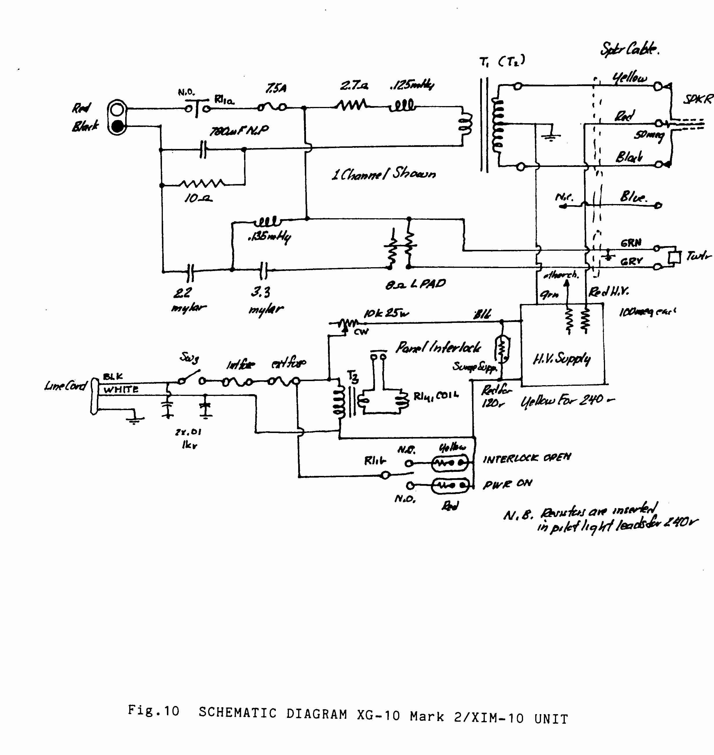
SCHEMATIC OF XIM-10
© 1980 - 2003 Wright Electroacoustics