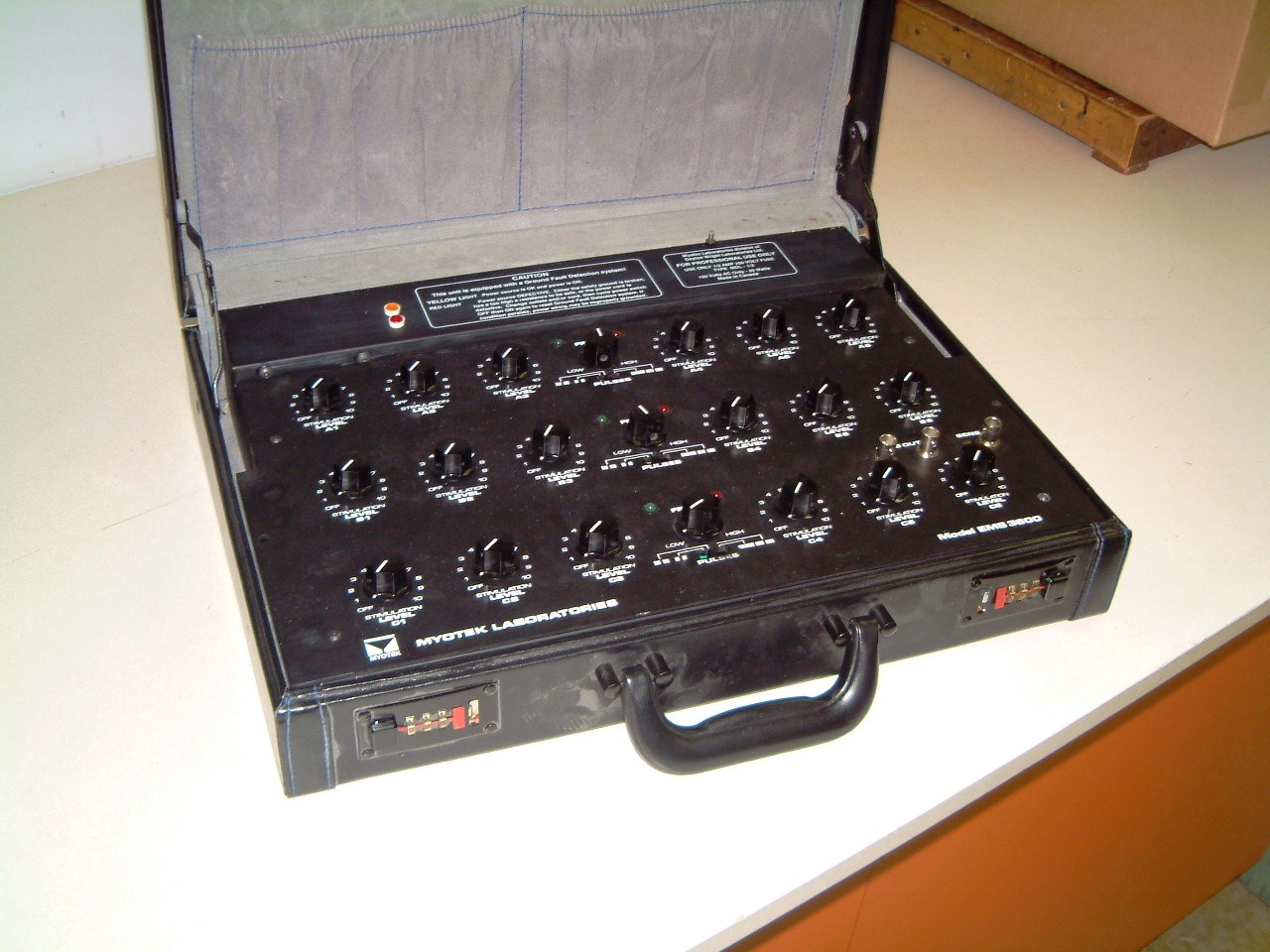
Featuring a complex TENS based system used to rejuvenate body muscles.
As can be seen, all the controls are labeled including their function.
The console is in the shape of a briefcase. At the extreme right side in the bottom row is a specialized pair of double TENS connectors, to the extreme right is a feedback connector for special emergency use.

Originally in the prototype unit the electrode connection pads were four to five inches in diameter; straps held each TENS electrode securely on the body wherever it was employed. Later it was found that the length of the extention cable placed too much of a load on the purity of the waveform; thus significantly reducing the rise time.
To correct this the length was reduced as well as using much smaller TENS electrodes.
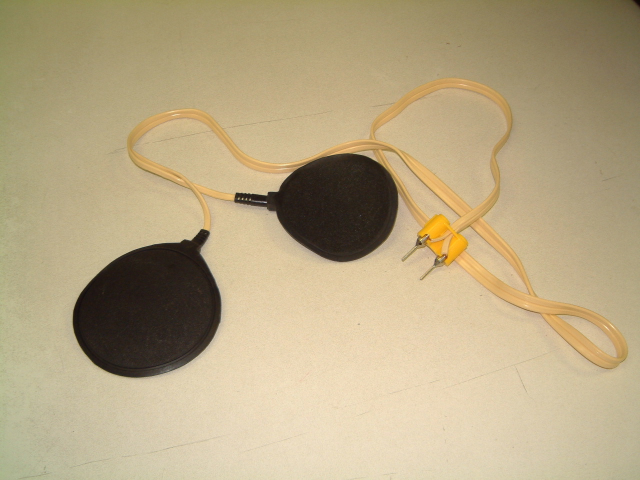
As can be seen in the photo's these larger electrodes required the TENS
electrodes
to be moistened with water, it had to
be applied to make the TENS electrodes function. However the use of water
did not make a very good contact with the skin.
This is the reason for the very arge size of the TENS electrodes.
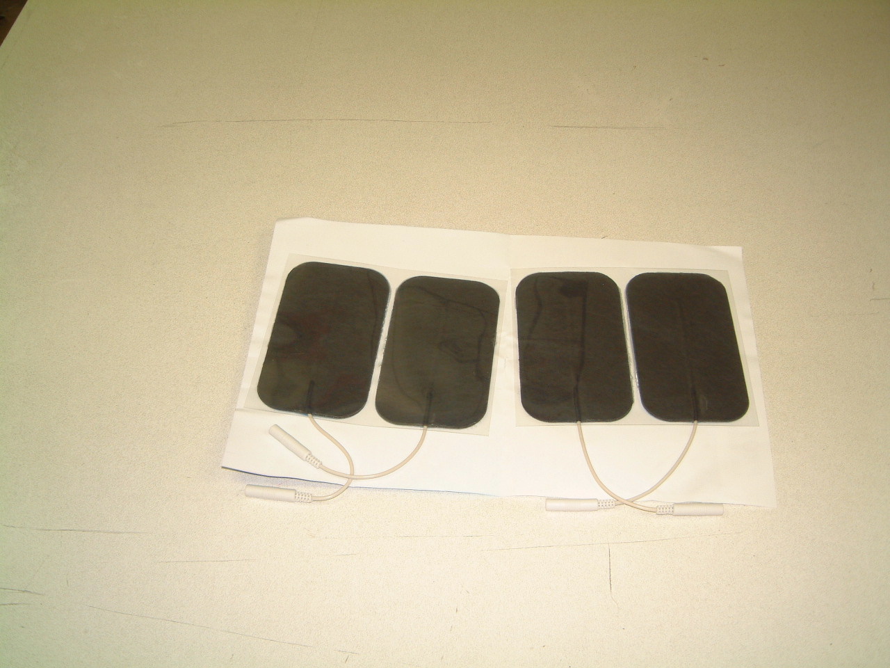
As may be inferred, these are much more efficient than the older ones as the modern type of TENS pads are self adhesive. The smaller sizes allows the placement of the TENS can be established quite accurately.
Remember that there are three separate TENS outputs and each of
the three contains
a seperate bank of outputs. The
result is that that there are a total of eighteen TENS outputs.
Specifications:
Tens output power adjustment controls / simulation:
When the control console is switched on for TENS stimilation there are too smaller indicators for each of the three putput banks. These are red and green. They will blink on and off to display the rate of the TENS stimulation
The knobs determine the intensity of the treatment. As can be seen, there are three banks of these knobs. For the first treatments we suggest levels of four to five. Then when a more vigorous treatment can be tolerated the setting may be advanced to eight.
Frequency degree control knob: This allows the frequency (rate) to be adjusted.
Frequency switch:
A) Continuous Mode. (I I I I I).
Continuous TENS pulse application without intervals. Application rate can
be
set to from 5 to 28 times per second.
This seems effective for chronic pain and many other points. The
small TENS electrodes may be applied to the acupuncture points.
B) Intermittent Mode. This allows selective settings allowing the muscle to be stimulated and then relax.
There are selections available.
TENS pulse duration time :I I I I :0.24 seconds.
TENS pulse duration time: I I I I I I :0.52 seconds.
TENS pulse duration time:I I I I I I I I :0.75 seconds.
TENS pulse interval time:I I I I :0.28 seconds.
TENS pulse interval time:I I I I I I :0.66 seconds
TENS pulse interval time:I I I I I I I I
:0.96 seconds.
Power: Isolated AC 115 to 125 volts.
Lights on the upper part of the console, this section is slightly elevated above the banks of control knobs:
If the larger yellow light is on when the power is on; the console is properly connected.
Warning, if the red light is
on when the power is on; the console has a faulty ground and is not
safe.
There is an exception at the bottom right hand side: There are two TENS
connectors there.
These are only used for very specialized TENS uses.
This device should never be used by children.
Be sure that it is never located adjacent to exposed water pipes, in bathrooms, or where plumbing fixtures are exposed.
Where in doubt about the reliability of available AC power, we suggest that a battery backup type UPS be employed.
Be cautious when the device is first used. The voltages used in the application of TENS are safe, but if improperly used as it can hurt people.
For that reason, DO NOT use it where the user has heart problems, or
has epilepsy
attacks or seizures.
Be certain that people that are using this device are properly qualified.
Always have a First Aid Kit available. It should include something like
smelling salts. If a patient has a unexpected reaction something like an
Epi-Pen should be available.
The R&D was begun in 1973 as an adjunct to another R&D program
that delt with percentile dimensioning data. We had been dealing with The
Natick Labs west of Boston
searching for dimensioning
data on people so we could design diving equipment for professionals.
We did some work for David Clark on some or their protoype designs when
they were using some of their data from the design of astronauts suits
adapting them to diving equipment.
However they persisted in the use of spherical faceplates ignoring the
serious aberration
effects caused by the diffent effects caused by air and water. On
some people the
visual distortion was so great as to cause nausea!
This led us to embark on a TENS based excesize system that if it could work on the ground might be adaptable to use in space where room was at a premium.
We had limits on our budget, so we had to construct a working prototype. We were confident that some errors would be obvious and could be easily be corrected. So on the second phase we chose a design that could fit into two or three briefcases. The first one could house the TENS apparatus and power supply.
It took me three months of spare time to produce somthing that was satisfactory.
It worked so well,
that it seemed worthwhile to invest in a set of silk screenes so I could
produce a black anodised aluminium case and use a white epoxy silk screenable
on
the panels. There
was enough room at the top of the case to house the power supply
and the connector
for the extention adaptor. The latter would plug into the rear of the
TENS unit and the
extentions were qutie long. But I found that using dummy loads that repliated
the larger set of TENS electrodes with the water based interface, the rise
time
seemed unsatisfactory.
I had to reduce the length of the extension cable. (Started
with 35% and had
to change this to 45%).
Also the large TENS pads were too large to apply TENS to smaller points.
We
decided to switch
to self-adhesive electrodes. The rise time problem was cured.