
DAYTON WRIGHT LIMITED
OVERVIEW:
Note: This version of the room contruction note differs from what was originally planned. To view the other plan, go to Yfacilities.html
One of very first decisions to be reached is defining the intended use of the room. Consider the possible choices.
- Audio
listening room
- Home
theater
- Recording
studio
- A
combination of all of them.
Then, several questions come to mind, such as:
How
much sound isolation from the outside will be needed?
Is
there much noise where the room is going to be located?
How
loud is it going to be inside the selected area?
Will there be any decor objectives that have to be considered?
What amount of seating will be needed and what type - will there be a mix - or
is any need for temporary seating? (eg: for any extra musicians).
What wattage of electrical supply will be necessary and is another distribution
box needed (separate from the main panel)?
Will any AC line filtering be required to suppress RF noise? (Consider possible
dimmer problems).
Does any type of battery back-up required (UPS) and on what supply lines?
Is a UPS needed (Uninterruptable Power Source) needed; and/or is it necessary
for only some critical apparatus?
Will any acoustic filtering be required for heater or air conditioning noise?
What speaker leads will have to be installed - and of what type and capacity -
will isolation and placement if these pose a problem?
What audio leads will have to be installed?
What video leads will have to be installed?
What co-ax/RF/CTV/Satelite leads will have to be installed?
What type of remote control leads will have to be installed?
What type of lighting control leads will have to be installed?
Is
the buildings AC power sufficient for all the pieces of apparatus, or is a
separate circuit breaker box needed?
Are
their enough duplex receptacles (AC outlets) provided for in the plans?
What about a possible expansion of dimmer control circuitry?
Will there be need for front projection/back projection installation?
Will there be a need for any projection screens?
Will low placed lighting be needed for reasons of safety?
Are
fire (smoke/CO) detectors needed?
Are
fire extinguishers needed, and if so, what class?
What building permits (include electrical air conditioning, heating, plumbing
etc.), are required before any construction begins?
Are
there adequate exits - including signs?
Are
battery powered emergency lights needed - and does the emergency and exit light
color comply with accepted local codes?
Has
air flow been planned such that the equipment has adequate cooling?
Is
there enough ventilation for the people occupying the room?
Are
there enough sound traps in the ventilation system for the people?
Is
the equipment being used sufficiently quiet so that it can be located inside
the room, or should some stuff be outside? Can it be located outside the the
room by the of remote controls?
Now I
think you can see why an outside consultant can be useful, especially in the
planning phases!
Any project starts with planning. Even if you are going to retain an architect or an acoustical planning consultant, he or she will need some sort of guidelines! Often some ideas might be useful. Many people save clippings in a scrapbook. By writing a commentary on which features you like, and what you dislike, can, in time, be of great assistance. It can also sharpen your critical skills. I can suggest a format that I found useful. Stick the clippings on the page facing your comments. Then, every so often review what you have saved, updating your notes.
Obviously, the longer that you have allowed yourself to think, before you have to make any critical decision, the more freedom you have; by keeping this scrapbook going, you will start to notice where compromises were made, and what effect they had. Remember that most successful projects required compromises, the art is in the effect that they had on the design and its success. Any multi-millionaire can afford to build almost anything; but its success depends on the skills of the designer. Certain of Frank Lloyd Wright's designs were not very good as homes. The kitchens were often too small and the layout's were often not very well suited to the residents. I am sure that you have heard the comment on "Falling Water". For several years, it was called "Leaking Water" until some things were fixed.
OBJECTIVES:
First, decide how and what the room is going to be employed - and is there going to be enough money available? If not, what has to be done first? Can some parts be delayed without jeopardizing the rest? One example comes to mind - the rooms ceiling! Does it have to act as an isolating barrier against transmitted noise? If the answer is yes; does it have to have a separate set of rafters and joists - interleaved and separately insulated?
Were is the electrical wiring going to be placed? Then, were are the speaker
cables going to be run? How about S-video cable - Co-ax for the TV, co-ax for
the Audio, co-ax for the HDTV, the three co-ax cables for the DVD's, the needed
remote controls as well as any wiring needed for the lighting? Will there be enough
air conditioning to cool the room - to cool the power amplifiers? What about
UPS's that may be needed to protect against surges and electrical
failures? What emergency lighting will be needed? Will CO and smoke detection
be needed? What about fire extinguishers?
ISOLATION:
Ceiling, floor and wall isolation have to br part of the planning. If the room is going to be in the basement, there are several considerations for the floor, especially it's a concrete slab below ground level. There must be a vapor barrier over the concrete! The seams have to be sealed as well. The vapor barrier must extend well above the wall, again, using sealing tape. Now all the other considerations come into play unless it is a free-standing room. Then any vapor barrier can be carried between two feet to three feet above the floor.
If the basement room is against one or more walls in the basement, the concrete walls have to be insulated, (and this must be what the building code allows for your area), you may be able to use 3" to 4" styrofoam as concrete wall insulation, BUT here any moisture will come in from the concrete wall itself! Therefore, the vapor barrier must (as for the floor), provide moisture protection from outside! Styrofoam is ideal as when it is installed and the seams properly taped, it stops the moisture from entering the basement. But, if the basement also has a washer, dryer, or shower - bathroom etc., there is already a source of moisture present from the stuff already there. Ths complicates the problem, slightly.
Therefore, let us concentrate on the basement floor for the time being. Once the (pick a heavy gauge polyethylene) for the vapor barrier, it is in place, the entire floor for the room should be covered with 1" x 3" furring strips for a sub floor to be nailed to, BE SURE that any nails or screws don't penetrate he vapor barrier. This sub floor can be stranboard with the waxed side underneath. This sub floor must be covered with another OFFSET layer so that the seams don't coincide. As the floor itself will reflect any sound, it should be carpeted. any industrial carpet may do, providing it has a durable under layer (or underlayment) that will nor degrade with pressure or time.
This is the time to consider if the floor should be level or in tiers. Basement rooms will have restrictions on the ceiling height. This is established by the building code of the area.
Sometimes special use rooms may qualify, but the plans for the room (and this is true for almost any construction), inside an existing building, must be submitted well beforehand in order to obtain any required building permit. Remember that any wiring (heating or air conditioning and plumbing MUST be inspected BEFORE any walls, floors or ceilings are covered. Most locations may have different inspectors for each trade.
Non-basement rooms, may have an entirely different set of problems. Sometimes a high ceilinged loft over a large garage, might be used. These same problems apply to other locations as well. The problem there is that the rafters above might be too small or too long, to support a heavy room. Sometimes several glue-lams beams may be needed to carry the weight of the room and all the equipment involved.
ROOM IN INTERIOR:
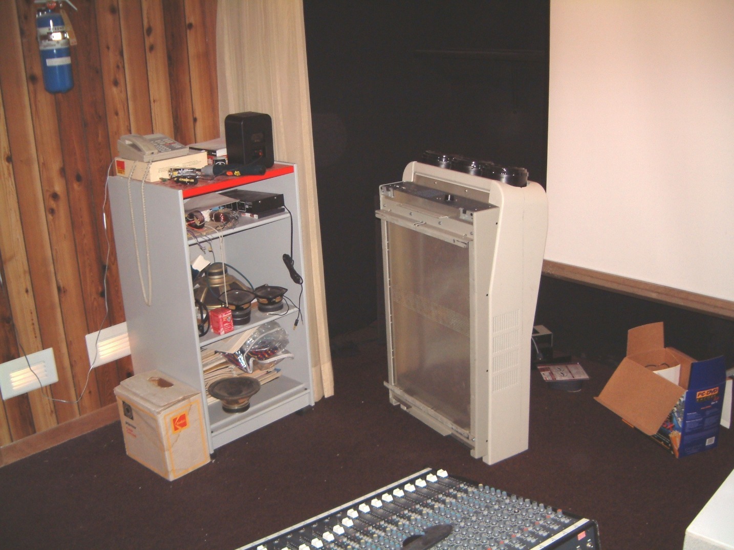
Consider that a free-standing room may be easier to construct as it may allow easier access to more of the rooms sides which may make it easier to install new cabling. I have found that if (for example) all the power amplifiers can be racked outside the room, there is less heat and noise to dissipate. A well designed room does not have to be a showcase for the latest 'goody' in the store. It may be better to have the CD, DVD and record racks inside the room!
Remember that double walls may be needed to prevent the transmission of sound and this applies to ceilings and floors. Walls may be built of interleaved 2" x 3" stud, using a 2' x 4" or a 2" x 6" plate under and above the studs. A double thickness of 1/2" dry wall with both the horizontal and vertical seams offset, is recommended. I lined the interior with 1/4" plywood cemented in place with liberal applications of vinyl based construction adhesive; the type that doesn't harden!
As a typical example, I left a 2" gap below and above the drywall which with the double plates above and below, allowed the use of a piece of 1" x 2" that was spaced about 3 1/2" from the bottom and 3 1/2" from the top, to form a runway for some of the unanticipated cables. With a baseboard and a wide foam urethane cove (or an a pre-primed extruded) molding spaced down from the ceiling, I was able to run a strip of rope-lights under the cove. I used a separate dimmer on the rope lights. Of course I stopped them at the vertical pieces of 1" x 6" in front of the curtain at both sided of the room.
ACOUSTICS:
I have found from experience, that a 2 x 3 foot room dimension seems best. Now of course the height of the ceiling is important; perhaps I should have made the dimensions 1 x 2 x 3 , or even 1 x 4 x 6! As the people have two ears, they tend to judge the effect by 'stereo' with ambiance playing an unknown factor. But when ambiance is missing, the effect is obvious! Therefore, the problem is one of creating the ambiance by means of longer time delays (combined with multiple time delays). However, the time delays MUST be randomized to prevent 'chatter effect' an illustration of this effect is what is heard when climbing up a long (interior) concrete staircase when there is no other masking sound.
I prefer the acoustics where a dead end / live end design is employed. This allows about a 10 to 15% stretching of the room. The dead end is padded with 4" of pre-painted black fiberglass stapled to vertical 1" x 4" battens, that were also pre-painted a flat black. I used a black roman-bridge woven fabric that didn't support combustion to cover the insulation. This padding extended on both sides of the front of the room all the way back to the curtain. I used a deep sepia red for the carpet. In other installations I have used a traverse (carpeted step) about 5" high as a divider. I aligned it so that the curtain was just 2" above it. This allowed a contrasting color to be used for the rest of the room. In one case, I used a near black carpet behind the curtain.
I think you can discern my intent; with the curtain closed I was able to focus the audience's attention of their surroundings. With the room lights lowered, the curtain was opened and either records or DVD's played without the distractions of seeing the equipment - in other words, what was being played was the important thing!
Now to the wall treatment behind - the live end. There I found that if I used a series of traverse tubes - thick (1/2") cardboard tubes with differing radii - cut lengthwise - and then covered with plaster daubed in place - the reflections were sufficiently randomized vertically such that the stereo imaging remained intact. I mentioned how important that a sense of ambiance is present. The curved forms on the rear wall combine with the ceiling reflections to create the multiplicity of time delays needed for the ambiance effect.
The only maintenance I have had to do, was when a heavy press was unloaded two lots down from our plant. Something very heavy was dropped and some of the interior plaster was cracked. The repair took about three hours. Otherwise, for almost twenty years there hasn't been any damage!
Over the twenty years after this room was built, there has been an updating of the room about every six to eight years. I removed the center portion of the wall mounted wooden rails and used a higher wall mounted support to the center speaker. Remember the large projection screen is not acoustically transparent as I would have wished. The process is one of iteration or refinement rather than a drastic change. There have been many changes in other equipment as well. One example is the use of self powered sub-woofers (where the equalization is built into the power amplifier). The use of multiple suspension systems for the voice coils allows for longer voice coil travel as well as more heat dissipation.
PROJECTION SYSTEM:
Initially, we started out with a Barco Graphics 400s system. We were able to buy the Barco 400 mixers. The set up was analogue with some expected problems with resolution. We then moved to a Barco Graphics 800s unit. As it was supported on a castor mounted mobile stand, resting on the carpet, it limited the floor space. We had used one of Max Gottchalk's solid wood adjustable rack system. This occupied about ten feet at the rear of the sound room. We soon realized that while it was OK for speaker testing, and fine for a limited amount of recording; when we wished to use it for mixed media, much a we admired it, it was too large.
The window into the room allowed us to see what was being tested - but the lights had to be set for the maximum illumination and prolonged testing, especially in the summer months could lead to heat exhaustion. A side effect was that by the fall, the room had developed a distinctively 'ripe' smell. As we used a fan mounted at the top of a 14" diameter tube with a series of randomly spaced baffles to ventilate the room, we needed an air conditioning connection to the fan. It could not be accomplished easily as the return air dumps into a plenum above all the offices. We are still working to solve the problem.
Well, we had to put up with it for three years. When a friend acquired a "Barco" suspension unit on E-Bay, I was interested. However, I used the quotation marks for a reason, it was not a Barco, but a mixed-breed that MIGHT be adaptable to the BARKO 800s projection unit. I even purchased an a mirror scanning type of Iris unit for it! It didn't work as it should have done. Perhaps, the projector was too low in relation to the screen. I could not raise it further. So I built a higher stand. After several hours of fiddling, the system was much better! But, I didn't need the Iris unit.
By the way, several projection TV dealers have started a rumor about"how difficult it is to dispose of Barco's because of the severe environmental impact", perhaps because of the lead glass used in the three tube faces. But the tree eight inch diameter lead glass faces contain less lead glass than a 17 inch monitor or a 19 inch TV screen! Give me a break! every so often I encounter this kind or crap - I should be used to it by now - but I'm not. The dealers spreading these rumors want to sell LED or TI reflection technology that needs a rotating (mechanical) color wheel to function. There are some obvious limitations on adapting these to refresh rate and the resolution of the screen; just as there are on flat screen monitors.
I must make it clear that I have been hit many times by rumors. If they are not tracked and countered immediately an immense amount of damage can be done. I know of seven small companies that suffered under the rumor mill to the point that their sales dropped so drastically that five went bankrupt. Unfortunately it seems to be the rep's for large companies that "feed" this garbage to dealers. It gets passed on by salesmen by the dealers who don't carry the line - often as the reason that they don't carry the line. I tracked down this sort of libelous behavior when a salesmen told his customer that the Dayton Wright Speakers were filled with propane. Then they told the customer that as propane is flammable when there is a leak in the Mylar diaphragm the prospective buyer blanched. His wife didn't want her husband to buy large speakers anyway. So the dealer's salesman switched them to a system with smaller speakers. I had a friend in the store that was so upset that he called me. I was able to fly to the dealer in Pennsylvania the next day and pick up my friend; we went to the dealer where we asked the same the salesman about Dayton Wright ESL's. He didn't know who I was. My friend knew the guy that owned the store. Again we asked the salesman if they were any other smaller speakers that didn't use propane in the speakers. He said "all of the DW speakers use propane in bags". The bottom line that his boss let him go. For almost two years the story didn't die. I had occasion to fly down to Tucson where I tracked down the store that had the same Sherman. Well, the libel laws in Arizona are much stiffer than they are in Pennsylvania. When I identified myself and informed the manager. He attempted to brush it off. I was able to get the store's manager to call his lawyer. When he found that he could be held liable for his salesman's action, the owner apologized. This seemed to stop the rumor!
To return, there is another consideration involved in BARCO Graphic 801s projection units. These are generally rated at 10,000 hours at normal brightness settings. If a second hand unit is purchased - look for patterns that have been burned into one or more of the tubes - generally the result of leaving it on the highest intensity setting with a fixed pattern! Any such pattern can be seen by reducing both the contrast and brightness and (using gray sunglasses) inspecting the face each tube in turn. A burn-in will be apparent! Now you must remember that to display the amount of hours on a BARCO Graphic 801s you have to go to the set-up "screen" where the number of hours is the last item. Remember that on BARCO Graphic 801s projectors the amount of time when the unit is powered and on stand-by, is also counted (even though the projection tubes ar not in use)! With the BARCO Graphic 808s Iris the stand-by time is not counted!
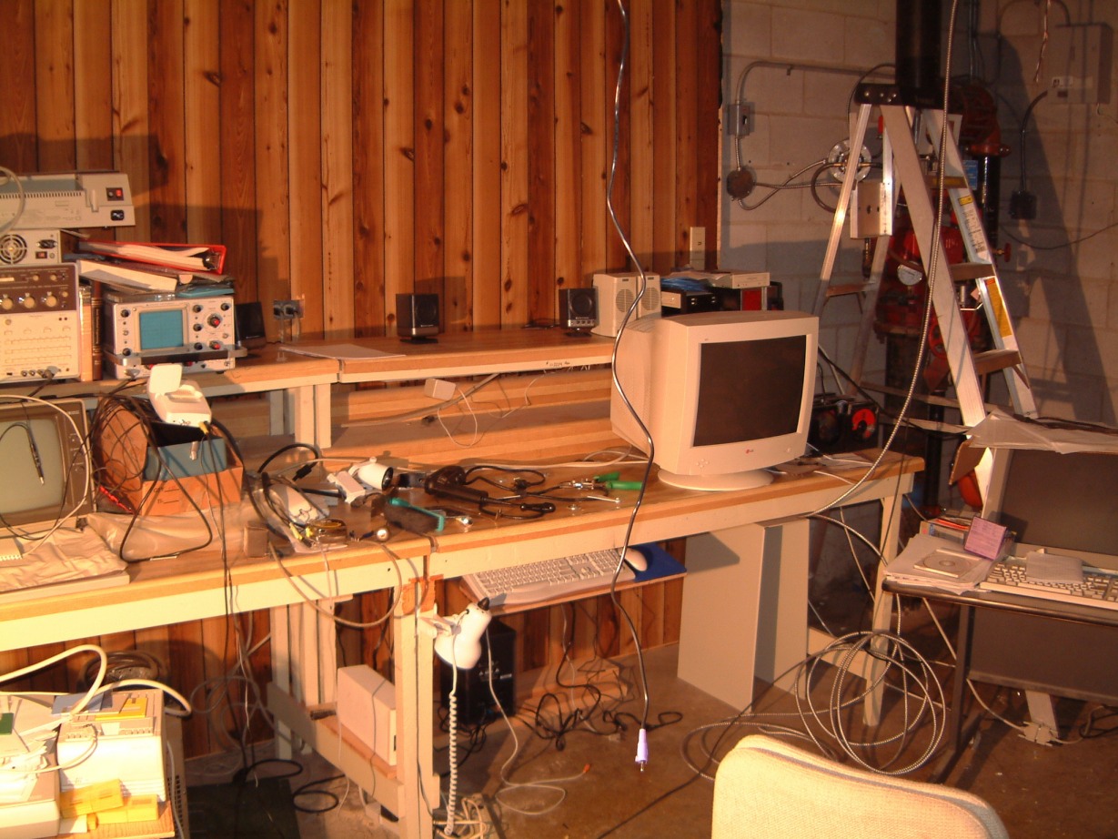
Even in the area that held some of the computers we use, the maze of cables on
the floor was driving me nuts. This is typical:

And this is when it has been untangled! I long for the long power bars made by Hammond that are long enough to plug in everything where the low voltage cables are long enough to reach. Alas, I really need a double row of duplex receptacles!
Real soon now, I have promised myself that I will make a triple row of the damned things - so that I can avoid phone extensions! I seem to be spending too much time with the installation either of telephone outlets or LAN jacks! Oh well, I seem to have accumulated enough different connection installation apparatus to equip a telephone exchange, a welding shop, a recording studio maintenance department, several audio and stereo shops.
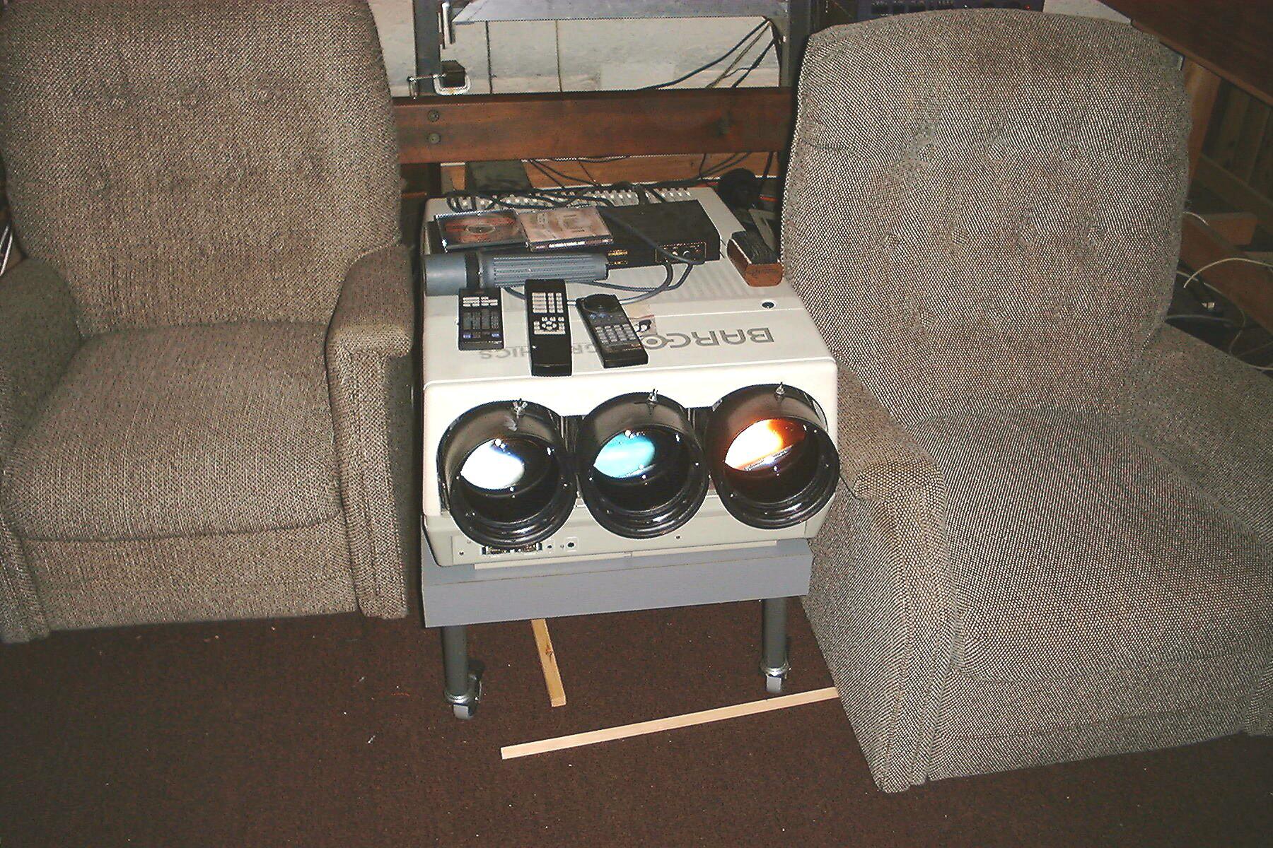
By August 2001, I had stumbled over the cabling too often. Even though all the cables ran behind the projector, they were still a pain! With some reluctance, I had to remove Max.'s large stand out of the rear of the room. This was a near impossibility with the Barco between the reclining seats. I wanted to put three or four seats at the rear of the room. This might required an elevated platform (about 10" high) across most of the with of the room. I could cut it short to clear a turntable stand that would house the preamp, the bass crossover unit and the record racks. I could move all the CD's and all the the DVD's outside the room and into the same type of IKEA cabinet that I was planning to used in the carpentry shop. The flimsy steel cabinets in the hallway were occupying needed floor space. By removing them I could widen the hallway by over three feet. Then below the IKEA cabinets I would have enough room for another computer, the 16 channel mixer, both tape recorders. In spite of the fact that the 16 channel mixer was beyond the window in the sound room wall, I could see what was in the room by using either one of the two wall mounted cameras inside the sound room itself.
I bit the bullet; the ceiling suspended Barco had to be installed! (Well, whenever I could arrange for two sprinkler heads to be moved. and could convince several people to help me).
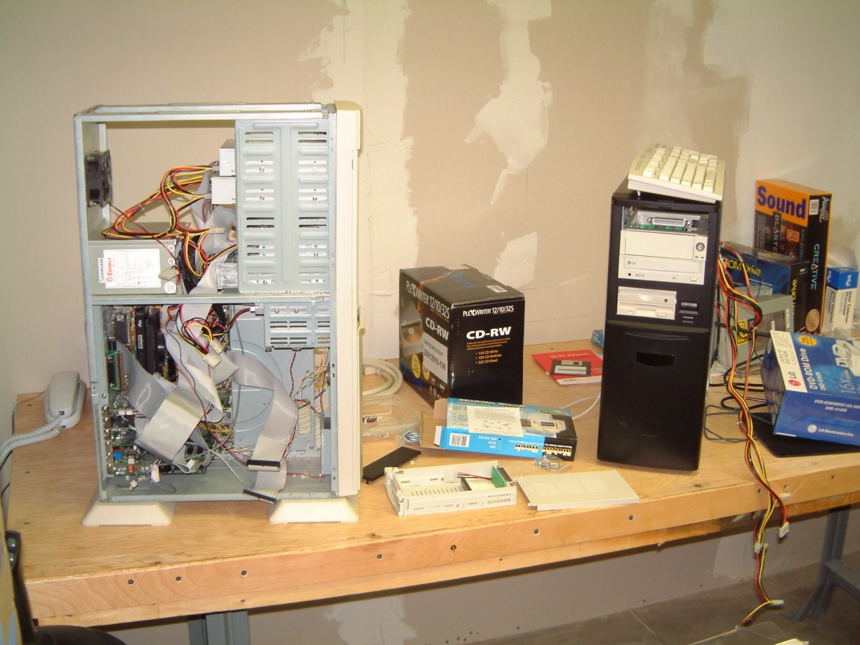
As a part of this, part of my computer 'lab' was already so crowded with in-use computers that ranged from '486's running Win 3.1 to Pentium !!!'s. This shows only a small part of the problem!
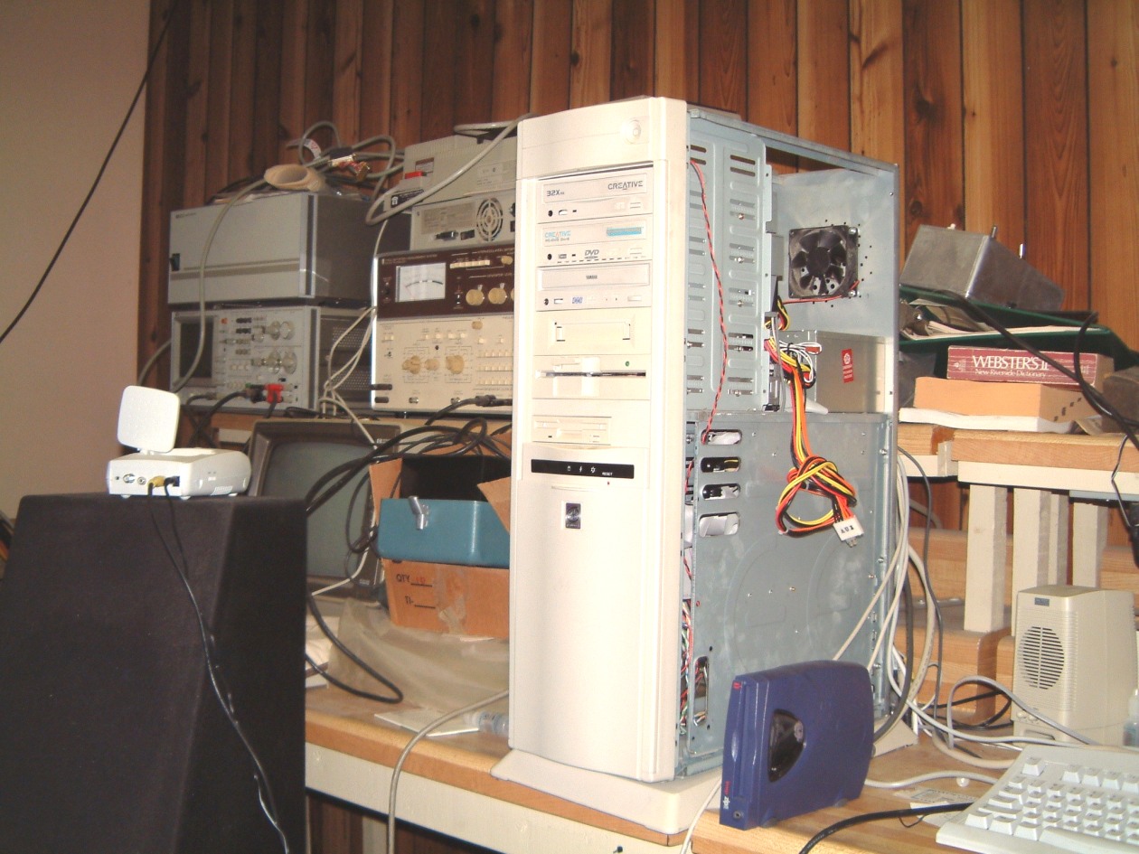
Another (I hope) faster Pentium !!! was awaiting space to be created so that it could be wheeled in. However, the rosewood equipment cabinet (?) still had to be moved out from the sound/media room to somewhere where it could be stored. As it weighed over 200 lbs, and was over eight feet long, this remained a bit of a problem! To complicate matters, there were too many cables that were 'threaded thro' the thing. Now, I was faced with finding the 'counter room' for a 200+ MHz Pentium 4 tower! This required three sets of five BNC cables, audio cables up the bazoob, S-Video wiring plus LAN connections to the Linux based server overhead on the mezanine level. I dislike boring vertical holes for the simple reason that even though we always measure several times AND cross check, something always seems to appear where it is not expected. I had an experienced carpenter drill some large holes into the bottom of a $600 waterproof fiberglass shipping case. I have to admit that the path from the place where he was drilling required negotiating several corners. Since that time I've always carried a compass!
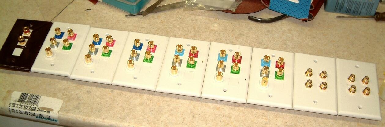
This shows just some of the various connectors and their mounting plates. Of course, I had to color code the BNC connectors; I've suffered too much already from mis-matched cables as even tagging the wires can create a problem when the profusion of tags either catches on something when the 'fish-wire' drags the wires through, or two or more masking tape tags get torn off - there seems to be a rule that prevents a single tag from getting torn off!
I was contemplating a trade for one of the 801s Barco Graphics in exchange for another video mixer or a sound modification device. As it is, I might not have the rack space for the patch bay I already have! It is another rule that the number of jacks needed always exceeds the space available. Even cross bar switches don't solve problems as it is another dictum that when a matrix switch gets noisy or fails, it seems to be where it is most difficult to access! More rack room!
RETURN TO THE CARPENTRY SHOP:
By October (2001), I was so crowded in the carpentry shop section that even building the a stand for the Barco 808s was an exercise in logistics. It required too much shifting around of stock to even reach the table saw! There was an obvious solution; when we moved into the plant in 1980, we had built two large racks to store ESL's. Each section was over eight feet in length by four feet wide. There was a top shelf, nine feet from the floor with a lower shelf about four and a half feet lower. Thus, we could store several pair of boxes or crates for speakers, while they were in the plant for maintenance.
I have to explain some of the problems. After Dayton Wright Group Ltd., shut down I was faced with the problem of the lease. As I had to personally guarantee the lease, I couldn't just walk away. There was also my guarantee to the bank as well.
It took me several years to clean everything up. D. W. Electrochemicals Ltd., was at 9005 Lesie Street, about a fifteen minute drive away from the 3-97 Newkirk Road Plant.. After I had to reorganize that company - D. W. Electrochemicals Ltd., - (the CEO hadn't made a single sale in four months). We had to work 40 - 60 hours a week just to keep it operating. In September 1991 the lease expired at the 9005 Leslie Street facility. So in late June, I made ready t move D. W. up to the former Dayton Wright Group Ltd., plant. I cleaned out the office space and built new counters. I laid new carpet over the tile, and repainted the offices. Everything had to be done in five weeks. Therefore about ten days before the lease expired we began the move! We were able to accomplish everything with two days to spare. building.
As we expected, we were horribly crowded for the first six months! When I was able to make time, I erected the needed partitions. It took us another four years to to roof over everything, and construct a stairway up to the mezzanine! By this time, D. W. Electrochemicals Ltd., was operating well.
Now, when I could take the time away from D. E W. L., I attempted to inventory all the parts and tried to find all of the manuals. By 2000, I was able to get this web-site operating. The websites operation brought offers from older customers, who allowed us to photostat the manuals. This saved us a immense amount of work as now we knew what we were missing. Most people understood that because the company had ceased operations due to because the bank, Dayton Wright Ltd., was a completely new entity.
For several years we no longer had access to the records or the stock that had been seized and disposed of. To put it in perspective, sorting out the old stock and completing a trial inventory taken took well over four years! Remember, that we were running another company at the same time!
That year (October 2001), I had finally got the essential part of the carpentry shop finished (well, not exactly finished - I had misplaced some if my router cutters and some bits and pieces such as flat bladed screwdrivers and chisels), it was sufficient to begin suspending the BARCO 800's. (as of June, 2004 it is still on a table). I decided to use a two by four foot piece of 3/4" plywood to bear the weight of the hanger. That way, the weight would be distributed over three 2" x 10" joists. Remember, the ceiling was carried by 2" x 6" rafters interspersed between the joists - but isolated from them with about 5" clearance between the top of each rafter and the floor above. I had used 4" of fiberglass loosely filled with about 2" of firmer (and denser) insulation as well. I used a 2' x 4' x 1/2" thick piece of medium density board under the plywood; it had clearance holes for the washers and locking type 5/16" nuts. With the hangers bolted in place the whole assembly weighed more than sixty pounds!
HANGERS FOR THE PROJECTION SYSTEM:
As I noted, installation was complicated by the two ceiling sprinklers, as they were aligned with the center line of the room. One of the heads would be immediately over the Barco projector if 9" above it. This proximity wouldn't have passed the fire code. However, if there were two heads; each one of which could be placed 3' from either side of the center line. This would work. As we had used the 'mezzanine' that ran above the main floor, for storage, I had to move a lot of stuff to clear the way for the sprinkler head 'drop pipes'. The result was that I finally found the ten missing SPA Mk 2 power supplies as well as fifty SPA preamp cases that someone had hidden away in 1984! I also found a S-Video VCR that had purchased myself at one or the CES shows in 'Vegas. So that made the effort worth while!
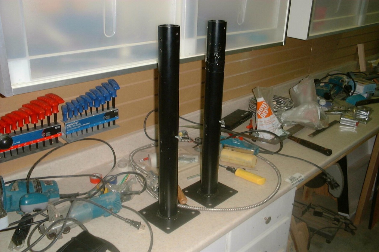
?? This is the actual hanger for the BARCO.
The hanger had to be place up on the floor of the mezzanine. I made a 3/4" thick plywood pad from a 2' x 4' piece of stock good-one-side, that was drilled to clear the steel tubes of the hanger. This had a heavy backing plate with many bolt holes. So that the nuts could be pre-tightened I used a piece of 1/2" thick piece of medium-density board underneath the plywood as a backer. Obviously clearance holes for the washers and nuts had to be part of this backer. The whole assembly would have three of the 2" x 10" floor joists to support it.
This may seem like overkill, but the mere thought of a heavy BARCO projector falling down staggers the imagination.
?? and this is the overhead mounting (inverted).
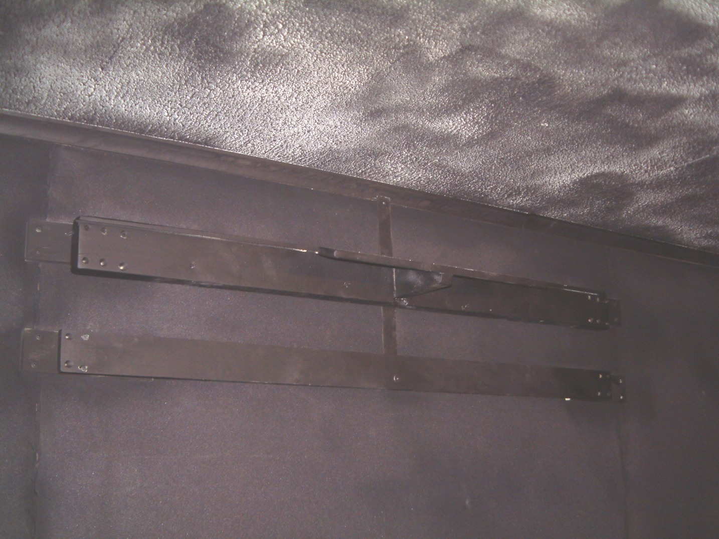
Here is a photo of the assembly - note that the larger tubes are mounted on the mezzanine floor, are above it in the photo (I was checking alignment at the time), whereas they will be below it once it is installed. Don't confuse the large rectangular plate (which is bolted to the mezzanine floor - the two large tubes project downward through the ceiling of the sound room) and the smaller tubes (that have the two square plates) are bolted to the 3/4 "plywood that acts as a support for the BARCO projector. Note that it operates upside down.
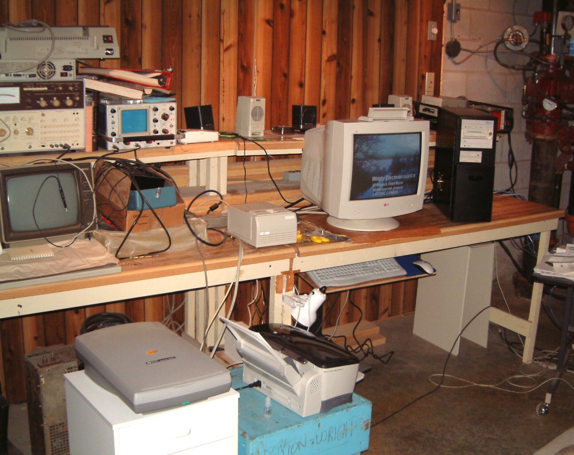
Well, as I said, the centered sprinkler head at the rear of the room, had to be replaced by two heads, over six feet apart! However, I decided that before I went to the trouble of lifting over 120 pounds of projector and installing it, the prudent thing to do, was to make ?($%@ it worked! Therefore I assembled the needed (my, there were a hell of a lot of them) cables, and test the thing where at least I could reach it! I had to relent and build another and higher stand (but now it more like a small table).
I took two photos. The one on the left, shows the Barco standing upright with a sixteen track mixer. The shot on the right shows the new stand, As you can see, I was boring vertical holes to accept the side ambiance speakers - hence the small stepladder.
 (Barco stand - less
Barco 801s)
(Barco stand - less
Barco 801s)
More chaos! I began to have increasingly fond memories of the simpler days when Stereo sound was new! Older systems had a single power amplifier, a preamp and a turntable; perhaps even an FM tuner! Then the wiring almost doubled - followed by bi-amping, with more wires.
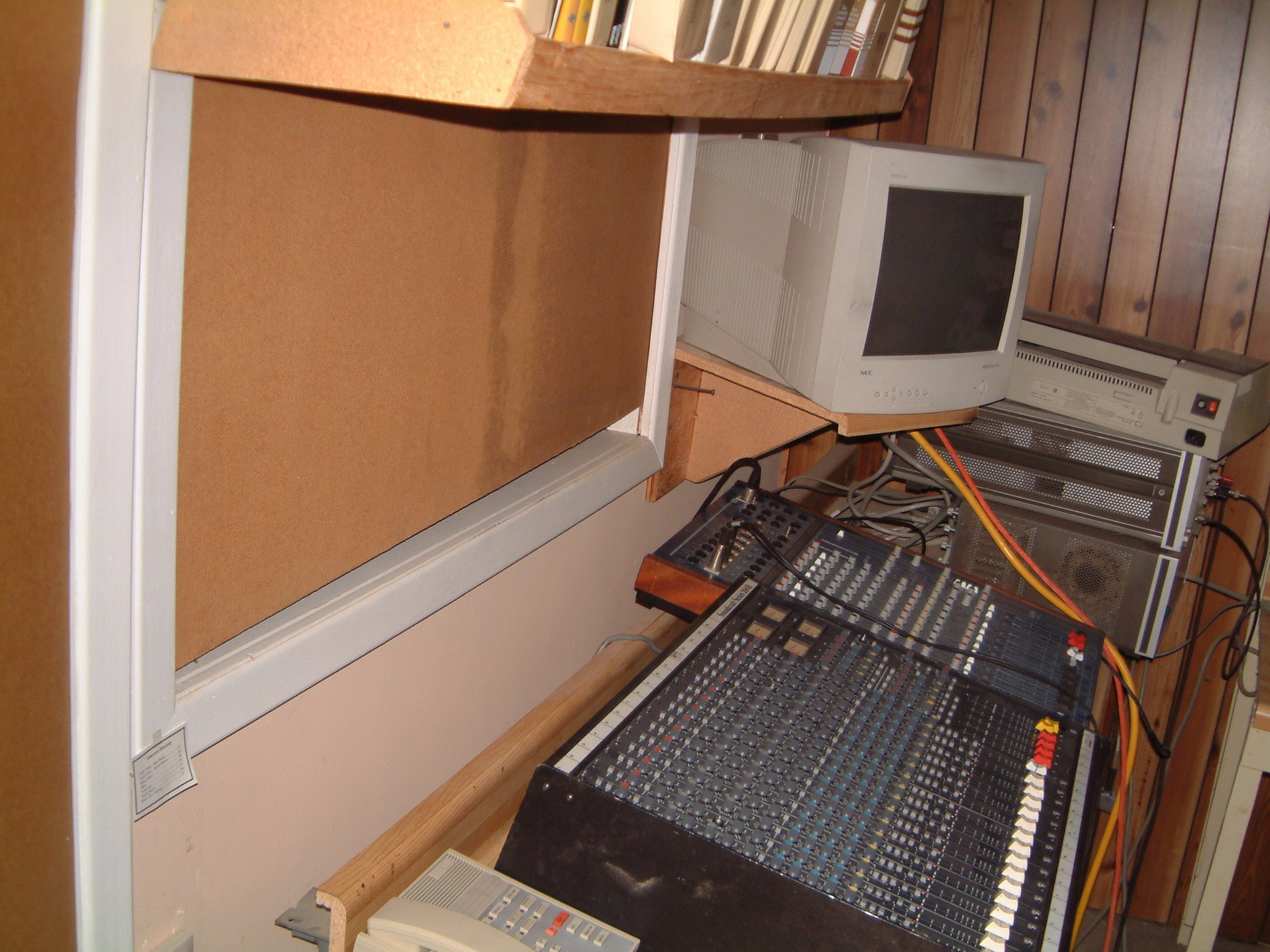
I decided that the two mixers (the old 8-channel and the newer 16 channel) had to be located under the window to the sound/media room. This involved moving the Yamaha MIDI keyboard into the sound room adjacent to the door. It fit! I would have to relocate the turntable (which was on Max.'s free-standing 'console') to a more conventional cabinet (still on a granite slab with felt absorbers underneath the slab).
The mixers would fit, providing I moved the old HP computer etc., that was connected to the Analyzer - Generator - Hard and floppy drives (plus a B-size plotter and an E size plotter) with IEEE 486 cables.
Pic of Barco 'table'.
The Soundcraft Series 200B mixer I purchased has a well known history including ground loop problems as documented in the 1995 article in EQ Magazine Maintenance Column by Eddie Ciletti
http://www.tangible-technology.com/articles/200b.html
which deals with the "Star Grounding" and ground loops. We had encountered this problem in 1958 in the Wright St. George exhibit, and on too many subsequent shows (from 1967 to 1987) - even to RF pickup from illegal RF finals used in Chicago cabs (1982).
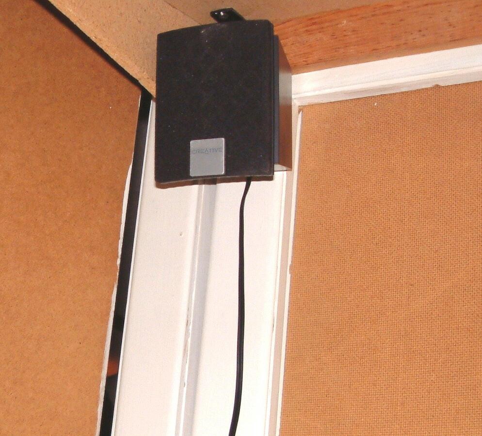
The next picture shows the mixers with the window (into the sound/media room). You can see the three Creative/Cambridge speakers mounted above the window. The surround sound speakers are mounted on the ceiling well behind the engineer. The speakers can be switched from monitoring the mixer (s), the sound in the room to the DVD sound feed from the DVD encoder to an actual DVD.
I decided to install a five channel speaker system from Creative Labs/Cambridge using three (left - center - right) small units at the window, and two rear surround sound speakers mounted behind my seat; using brackets that would be screwed to the overhead joists. These brackets would place these units about five and a half feet apart and six inches below the dropped ceiling.
Note the use of self-adhesive plastic wire guides (mfg. by Wiremold Chromate (R) C110 white) to dress-up the wiring. Note also the scar where I had to use a router-trimmmer to remove the sliding Masonite cover on the window. Installed in 1982 well before the dropped ceiling was contemplated, I found that it was jamming after the small hole that was needed to raise up, wore through the material. We had a black-sandblasted-anodised that we had made to use, but it was never installed. It has misplaced somewhere in our plant and I have ever been able to find it. But I located the drawing and the bushing that we intended to use with the linen cord, pulleys etc., so now that everything has been found I have no more excuses. (In order to use the Barco Iris, the room has to exclude other light sources).
The computer is under the bench and is equipped with the ability to accept six sources for the video signal ( The obvious ones are the feed to the Barco, the feed to the computer (showing the mixing programs), the feed from any DVD that is being played on the computer, and any two feeds from a camera. By a rare stroke of luck, had bought an Inline (tm) IN3506 RGBS switchers with a 500 Mhz video bandwidth which should suffice. In addition, we will be able to monitor any audio source. We will have a choice of DTS or Dolby Digital monitoring and encoding.

As you know, digital mixers are now used for most productions - even digital microphones are common. But there still exists a demand for 'natural' sound; that is not fatiguing for long-term listening. I do not have the space for anything more elaborate than whatever I can stuff into the allocated space. I have been considering various software programs they will give me the option of Dolby digital or DTS encoding on the computer.
As I remarked a month (or more) ago, I had constructed a stand to hold the Barco 801s (Iris) projector. (Barco stand - less Barco 801s) As you can see, I badly needed the space, so I finally set it up on its stand!
 As it was too heavy to move myself, I had to wait until I could find another
'warm body' to help me lift it up to the castored stand! At the lower center of
the image, you can see the small lens of the Iris (tm) unit. I
focussed the projector and realized that the image was much sharper! I can't
wait until my Radeon 8500 128 meg unit (TV) board installed. From what I know,
I could use the Yamaha 2200 SCSI unit or opt for a LaCie Firewire board based
drive for a burner to make recordings. I might have to wait until the HDTV
standards are finally established. If they are changed again, there will be a
lot of 'pissed-off' people out there!
As it was too heavy to move myself, I had to wait until I could find another
'warm body' to help me lift it up to the castored stand! At the lower center of
the image, you can see the small lens of the Iris (tm) unit. I
focussed the projector and realized that the image was much sharper! I can't
wait until my Radeon 8500 128 meg unit (TV) board installed. From what I know,
I could use the Yamaha 2200 SCSI unit or opt for a LaCie Firewire board based
drive for a burner to make recordings. I might have to wait until the HDTV
standards are finally established. If they are changed again, there will be a
lot of 'pissed-off' people out there!
Oh well, perhaps the consumer expects to be shafted once again. We can only wait and see!
As expected, there was some difficulties in suspending a heavy 20" HP monitor. This was selected because it allowed selection between the more normal three row of pins and BNC connections. As this monitor was used in CAD-CAM designing, it had high resolution (over 1600 lines) and a high refresh rate.
But, it needed to be suspended from the overhead rafters (in this case 2" x 8"'s - remember that the area had a double ceiling). First the 2' x 4' ceiling tile had to be removed. Oh well. it had to be done anyway to run the wiring to the rear surround sound speakers. The exposure the the wall above the tile rails kicked over the realization that a hell of a lot more BNC wiring had yet to be done + the audio and LAN connectors as well; I was also installing pass-thro mike connectors to handle at least twenty microphones.
Now, I had to find a hanger for the monitor. I tried the internet. It had some but they seemed to massive to be easily installed. I did not need the type of TV hanger that you see in banks! I found one that sold under the name "PrimeTime" manufactured by Vantage Products Corp., in Santa Fe Springs, CA.

As you can see, I had to use two 1/2 inch MDF spacers to add some extra reinforcing as I could not be sure I could locate it the center of the 2" x 8". This way, I could spread the load across three rafters. I added the 1" x 2" spacers so that I could be sure of getting the lag bolts in to the centers of several of the 2" x 8" 's. I also had another constraint in that I would have to install the stuff by myself. This limited the weight of each bit. The shot was the pre-assembly to make sure that it all fit! The actual job would be done by assembling the pieces one at a time. Then I removed the U-shaped steel-tube hanger.
It took two weeks to get it into its position final position. It weighed just enough that I could not support it long enough to drill the holes for the six-inch long lag screws, remember that the supporting frame was about one and a half inches in thickness including the three 1" x 2" x 14" strips that were glued and screwed in place. We decided that the monitor could be several inches to the left without harming the "sound image". I had to pre-cut three more pieces of 1" x 2" x 14" to glue and screw up to the 1/2" plywood "overhead". To make certain that I was centered under the joists I drilled several 2" holes in the plywood. I hit the center of all three. I drilled several additional holes for cables while I was at it.
I had not realized that you could purchase steel drywall screws 4" long. Pre-drilling was not needed for the joists which simplified the mounting of the plate. Only after it was secured, was it necessary to use the lag-screws.
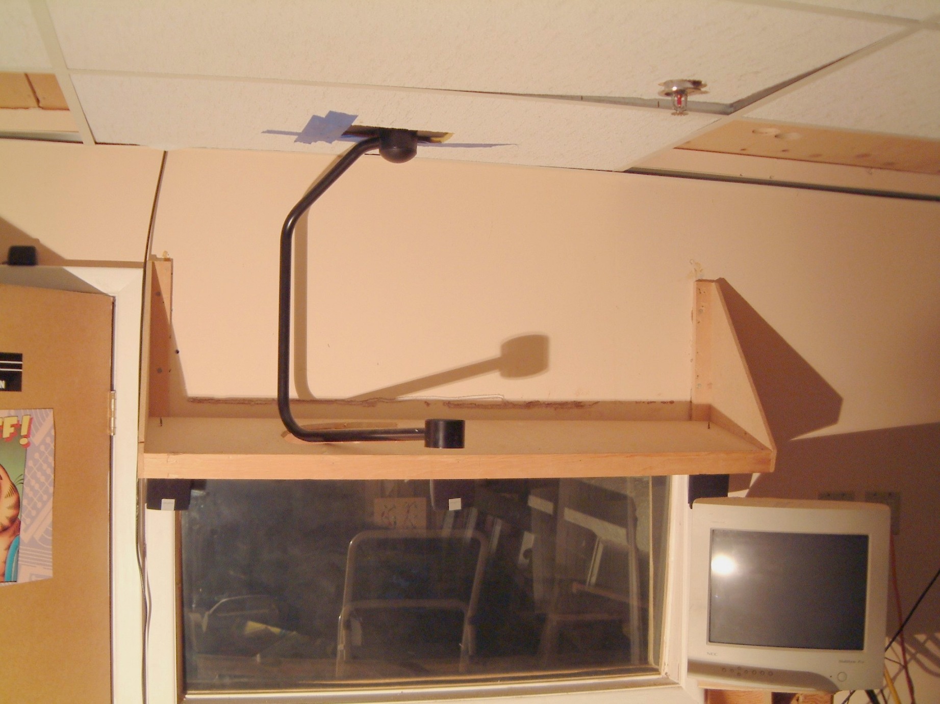
The shot (about February 2003) shows the hanger in position (less the monitor). The 2' x 4' foot hanging panel was slightly off-center thus the duct-tape used to mark the exact position of the clearance holes. We always seem to have a plentiful amount of these panels; most of the BX and other wiring is secured to the wooden joists and covered by the panels.
I have purchased the various wall plates but I'm still waiting for the BNC cables and the crimp type MIL connectors (not to mention the crimping tool itself - I have a superb collection already - however it is the one tool that I missing from the twenty-eight that I can locate!
I am constantly surprised by the lowering of the prices; for example, now the cost of a good DVD player is about $250. The connecting wires are about $90 (for a ten foot set from the TV to the DVD + the cost of an optical cable (another $90) + the cost of all the speaker wiring (over $200 for four speakers (two on either side and two to the rear) and a center speaker as well. Oh, I forgot the subwoofer! Another $25 for an RCA-type cable (assuming a powered subwoofer) - - - Oh and the receiver; obviously digital (God how I miss the large knob that you used to tune the station! Now the front panel (usually black and engraved with 5 point type - which you need a flashlight to read in the home and enough buttons add doo-dads to fly an aircraft!) Heavens, somewhere I left out cost of the receiver + the cost of all the batteries for all the remote controls you need to operate this sucker! Did I forget the cost of acquiring a degree needed to actually turn on the power? I had been retained a long time ago to locate a less costly source for exotic loudspeaker wire. Now I can say that the actual cost of the wire itself is far, far less than anyone could imagine. The connectors are manufactured by the use of automatic multiple head turret lathes, the actual gold plating is just a series of flash plantings and a hell of a lot of the cost is absorbed by fancy packaging! (Tell me just why it is more difficult to open the packaging for a set of cables than it is to perform brain surgery?)
I promise that when all connecting cables are hooked up, I'll show a shot here (if I can lay them out on the floor)! But, if not, I might have to run them in the ceiling. Whatever, I may have to instal the ropelights over the wider cove molding about the same time. I might also have to get rid of all the dimmers, and resort to a centrally controlled lighting system. We'll see.
By this time my desk was overflowing with programs and papers. We were so busy that everything had to wait until I had made the time to erect the supports and install the new wiring.
 This is what I can face when I am behind. Floppy disks litter the desk as I am
frequently interrupted with telephone calls from stock brokers who have
purchased my name from a directory. This is why I never give my full name when
I register software. I am able (sometimes) to back track a "deliberately
misspelled" name to a software vendor. As current laws prohibit the use of
names without permission in advance, I can usually stop any further spread.
Well, at least I can make the attempt!
This is what I can face when I am behind. Floppy disks litter the desk as I am
frequently interrupted with telephone calls from stock brokers who have
purchased my name from a directory. This is why I never give my full name when
I register software. I am able (sometimes) to back track a "deliberately
misspelled" name to a software vendor. As current laws prohibit the use of
names without permission in advance, I can usually stop any further spread.
Well, at least I can make the attempt!
To put this in context, this is about 25% of my desk. The so-called "paperless office" has at least increased the amount of 'stuff' by a factor of ten!
Although,
at Dayton Wright Associates Ltd., we produced several "array sets" of
the XG8's using the Extruded Aluminum Cabinets (these were produced in 1
x 2, 2 x 2, and 3 x 2 - as an example a 1 x 2 array had two stacked ESl's by
one ESL wide). When we began to offer the wood trimmed steel cabinets, we
made several stacked pair - for trade show demos. All of these were snapped up
when the show was over. Then, Leigh Instruments bought the company
When I bought the company from Leigh, all of the extrusions had been sold. (the price for aluminum had shot up by that time). Therefore, we took the steel cabinets (most of which were covered with rust - had them sandblasted, primed, spray-painted and baked.
About every two months we'd have a request for a quotation on stacked IM10's. About 35% resulted in orders with the majority with a Rosewood finish. Most of the photo's we took at the time were in one file at the time when our bank loan was called. We recovered a stacked set that were put into storage. The storage warehouse rent payments were in arrears, and some of the stuff was (illegally) auctioned off - generally from customers who had moved to other provinces or even to California. We received a call from a guy who was opening a roller rink requesting assistance in how to connect the stacked ESL's. From his description (Oak with Wheat grill cloth), I realized that we had only sold one pair. The customer had moved to Oakland, California several years before and had the receipts to prove that the storage charges had been paid. (I have had numerous cases where preamplifiers have been stolen - and someone has taken the item to a store to have it fixed - usually the power supply is missing. We have tried to keep records of where it was sold and if the warranty card was returned, who was the original owner.
But, in this instance, I knew the customer. I called him and asked if his ESL's were missing. In turn, he phoned the storage company ( and tracked them down to another phone number). He was unsatisfied with the answer so I called the police in the area and had them check the serial numbers and the description. These were the stolen stacked IM10's. I called California and our customer called the police. He was able to satisfy them that the IM10's had been stolen. The police got a warrant and seized them, (with obvious difficulty) and had them taken to their evidence room.
The thief didn't have the money to pay for all the stuff he had stolen, so he was sent to prison.
About nine months later, we received a panic call from the police asking us to come and pick the #*?^@ ESL's up immediately. I attempted to be gracious as I told them that we didn't have a truck; anyway, wasn't it was their problem? I received a much more subdued phone call an hour later. Now the said that they had received permission to use one of their 'paddy wagons' and they collar as many people as needed, if we would please store the stuff in our plant. I said that I had to call California and get an OK. When I got it I called the police and told them that the owner had given his permission. Within an hour they were there at our loading door with their driver and three off duty cops.
It was a week later when I had the free time to I check the sub-woofers. As I expected, I found that all of them were fried. So, conscious of the acrid smell of the ST-300, I connected the ESL's and found that the HV transformer somehow had been connected to a 220 volt outlet. NFG. I located two adapter cables and unpacked two new IM-10's. I let the ESL's charge for several days. When I conceded an old McIntosh 200 watt tube power amplifier, several electrodes arced, destroyed, perhaps by the storage warehouse owner who might have tried to use the system himself before he (illegally) sold them to a roller rink. It tool me several years to dispose of them, as is; the owner in California didn't want them anymore and gave me the OK to sell them.
They finally found a new home. We had enough type HS Mylar to fix them. There were some of the Stacked Pair of XG-8's and IM10's we produced in steel cabinets. When we were manufacturing anodized aluminum cabinets we must have made over 35 pair of four speaker arrays (that's 16 ESL's for stereo) and even some larger six speaker arrays (that's 24 ESL's for stereo). We had a color photograph of that array after it was installed in the US, however, when Leigh transferred the company to Waterloo most of the photo archives (including my personal stuff) just wasn't there. Much later, after I purchased the company back I was able to find some of my five, four drawer filing cabinets. Leigh wanted the PendaFlex folders. The individual files had been dumped into large wooden crates. I spent several months in sorting out what I was able. But a lot of the photo's were missing.
I just received an excellent photograph of a "Stacked Pair' of ESL's" made by a customer. Here is the photo.
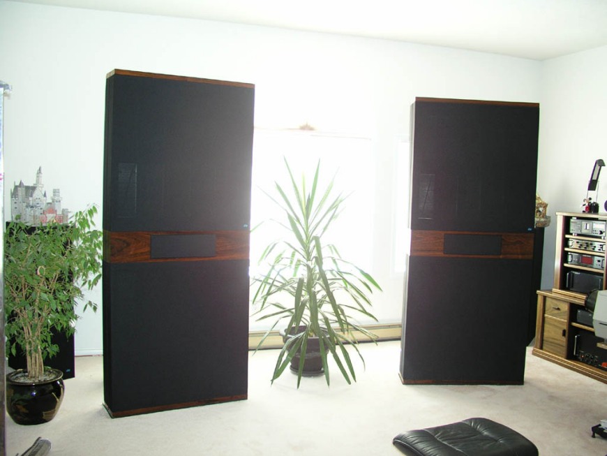
This is typical of how they looked. But in this case the owner had made some of the exertions himself.
FURTHER REVISIONS:
After I had been using the room for auditions of some pre-recorded tapes that were produced by using digital mixers, I found that (sometimes) there had to be a slight ambiance fill-in from the sides. I decided that would have to make provision for the installation of two small speakers on the side walls of the listening room. By experimenting I found that the old Hafler system (which connected the side wall speakers in series so that the right and left outputs of the power amplifier did not use the (ground) of the amplifier, but used a 15 ohm (50 watt) resistor in series with the right and left ambiance speakers that would be installed on both sides, about half way along the side walls. These speakers would be tilted upward at about a 15 degree angle - close to the ceiling.

illustration of speaker mounting and terminals
As I was rewiring the six and a half foot wide aisle in preparation for installing a counter; (this would be needed for the sixteen channel mixer), I realized that I would need some more wiring. I had planned to move the new Pentium 4 based computer into the same aisle. Therefore, I needed an extra four duplex receptacles on a a ten gauge BX service. I would also need TV coax, code 5 LAN and telephone connections in that same aisle. The sound room now had several racks of CD's and DVD's not to mention bins for records! As I had reached the point where I had run out of space, now everything I wanted to do became a matter of logistics. For example, before I could move Max.'s console out. I had to build two IKEA cabinets in the same way as I had done in the carpentry shop. That would provide the storage space for the CD's and DVD's. I would also have space for fifteen reels of tape plus twenty of my critical records. With the two 44" cabinets up on the wall, I would have the clearance needed for the move. Nothing is quite as simple as you think it will be.
As the side wall ambiance speakers needed both a hanger, I went to Home Depot and bought a set of AVF Vector Surround Sound Speaker Wall Mounts 100. While I was there, I decided to employ the Leviton QuickPort system. (I tried the Carlon Low Voltage Outlet Boxes, which I found very difficult to use - first the self-tappind screws were too tight - requiring that they had to be pre-tightened on the bench to stop the screws from locking-up ? then, after ten minutes of frustration I found that the plastic boxes didn't have enough clearance to use the Leviton QuickPort system. Therefore I returned to purchase a pair of Thomas ? Betts (Iberville) WBF-1 PosiMount Low voltage metal mounting wall internal plate. These would carry a pair of terminals for the loudspeakers (plus a blank lower insert). As I was planning to consolidate as much of the wiring as possible inside the walls, this same system would also take care of the 72 ohm BNC (six cables) and the S-Video cables as well. The more I have to deal with complicated snarls of wiring, the more of a sucker I am for order. Well, I have to admit that this does not apply to my office!
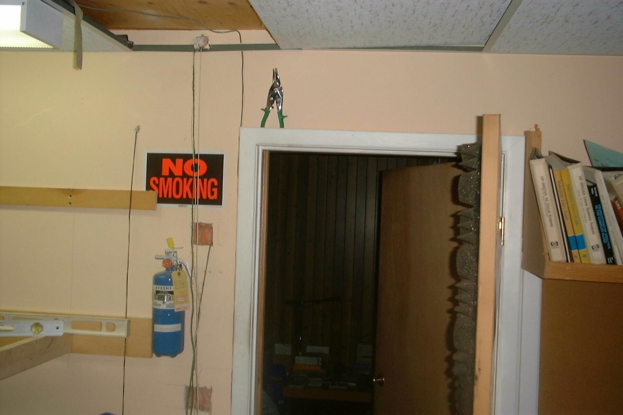
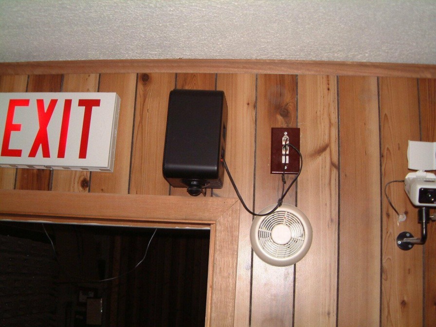
In the above photo, you can see the cord that was fished through the wall so that the BX cable could be pulled into place. The upper opening is for the telephone, the co-ax cable and the LAN connection. Lower down is the light switch and a single duplex receptacle for one of the cameras mounted at the side of the sound room.
The same Carlon Low Voltage Outlet Boxes would be used for as much of the various types of low voltage wiring as we used in the sound media room and the adjacent hallway. As we had installed a fireproof door in the wall to the computer room, and the sound room had an additional exit and all were posted with lit Exit signs, we could block off the short hall once we had moved Max.'s console out of the room. Understandably, an extreme amount of pre-measuring had to be done. We were so short of space that if anything couldn't be moved easily, we couldn't afford to let it obstruct the hallway. The whole thing became an exercise in logistics.

preparation of wall for IKEA cabinets
Side wall mounted ambiance speakers were installed using the 'Hafler' series connection connection. In this configuration, the side-wall ambiance speakers are connected in series without a common 'ground' return - this, in effect, enhances the difference signals. A 30 - to 50 ohm 25 watt series resistor is needed for the subtle enhancement to operate correctly. This makes the rear mounted ambiance loudspeakers less overpowering without detracting from the stereo effect from sounds such as aircraft fly-by's and similar effects.
The wiring shown was temporary, the interconnecting wiring had yet to be permanently installed. This is a 'sound' procedure (to make a bad pun) as inspite of the use of color coding, errors do occur. For example, I have found that in about 20% of store demonstration installations it is not uncommon for mis-phasing errors to occur. Often the level of demonstrations is so high that the listening fatigue level is so extreme that the salesmen cannot spot the error!
Part way through this work I decided to switch my sound card from 5.1 to 6.1 (and eventually to 7.1). This will be shown later.
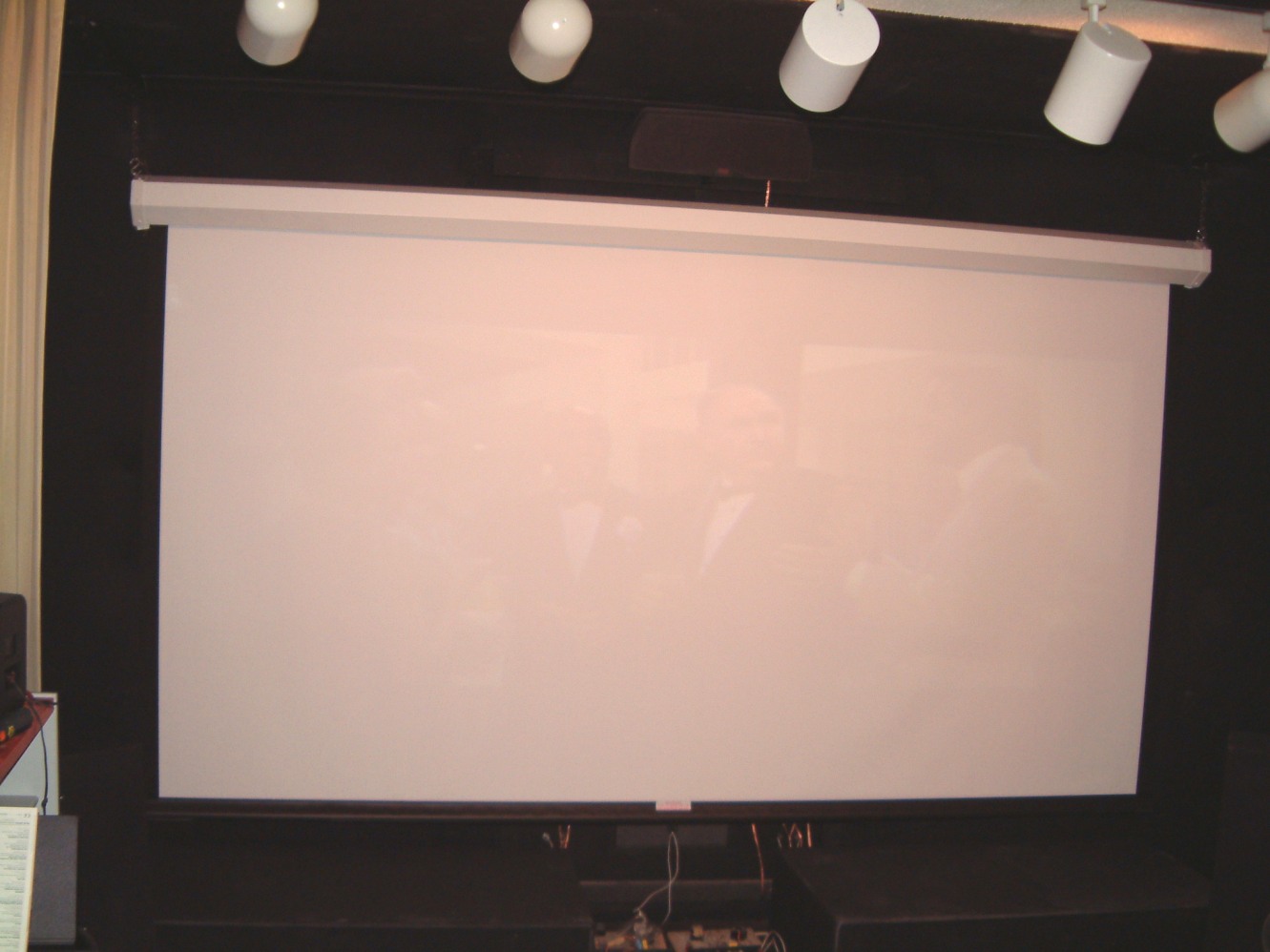
Now, as I had purchased a much larger screen (about 120" wide x 84" high) the older floor stand mounted screen had to be retired. The old one was terrible even though I taped the carpet to locate the three legs of the stand, every time I had to reposition anything at that end of the room, the screen had to be lowered. When it had to be used, the Barco had focus problems! This involved another fifteen minutes of work with the lighting level set at the highest level to adjust the legs once more. The stand wasn't stable!
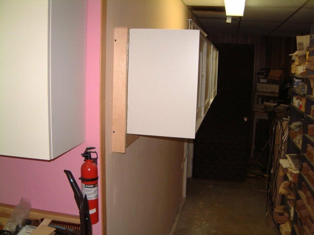
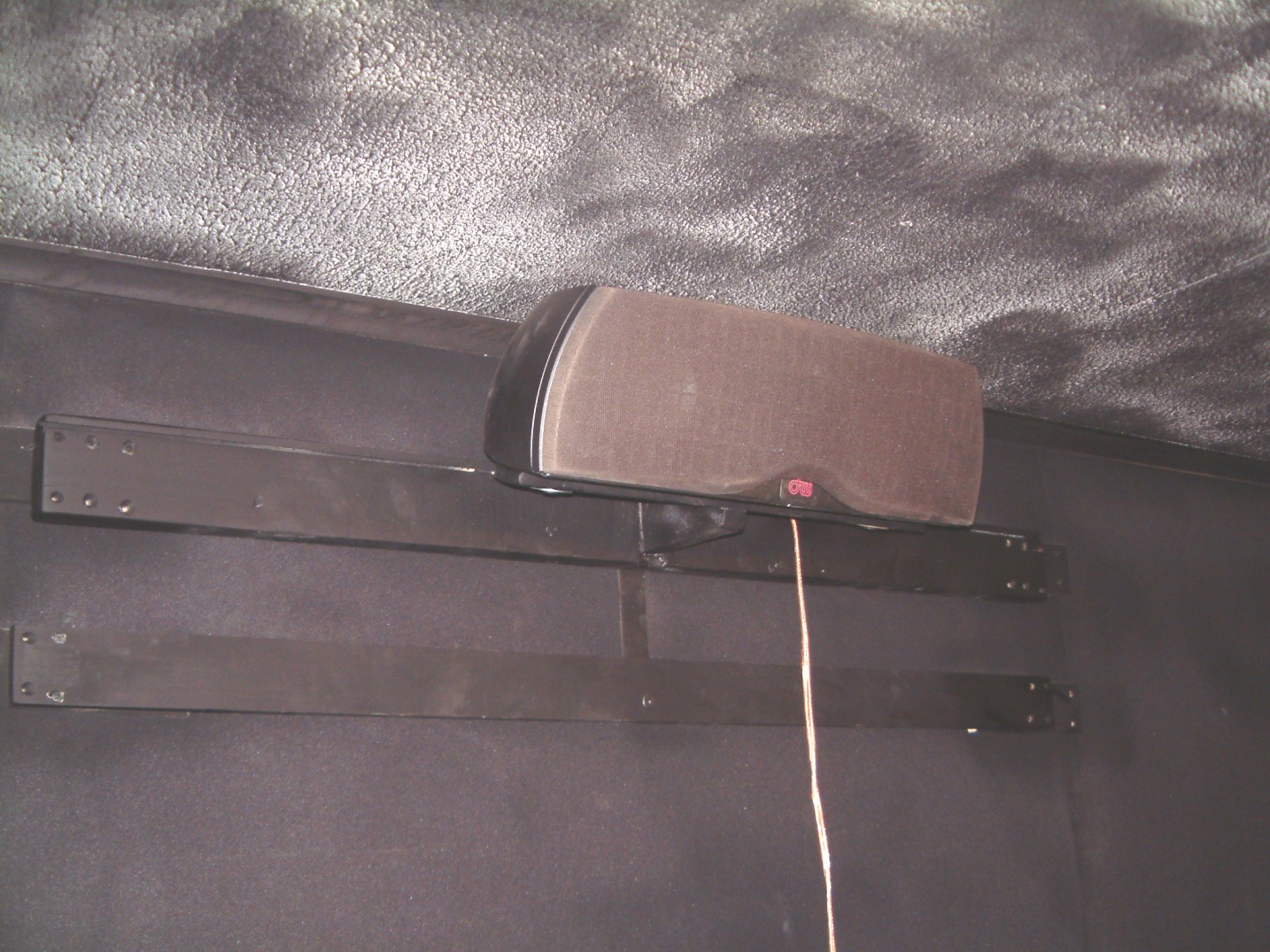
When I switched to 5 channel sound, the location of the center speaker was two feet off the floor. I realized that a better location would be as close to the roof as possible. I could always install a 4' wide and 3' long x 2" thick black felt pad on the ceiling of the room. Well, this required me to make an appropriate mounting for the center speaker. As I had used a defective JBL center speaker unit after replacing the three drivers with Focal speakers (and modified the crossover network), all I had to do was make a mount for this unit.
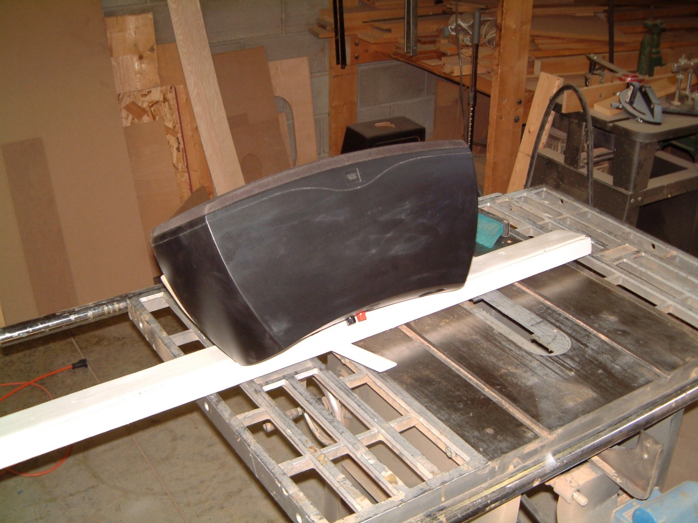
The upper photo shows the speaker from the (almost) top. The lower photo shows more of the mounting for the center speaker. Note that the mounting is painted in a flat white. This makes it much easier to see what you are doing. Any new markings are easy to see. And when it is ready to go, the surface can be resprayed with flat black. This will hide any ball point pen marks. Of course, the center speaker was removed before spraying! I always use oversize holes (in this case 5/8" and use 1 1/2" x 5/6" washers. The washers are bright as I haven't used a chemical "blackner" to treat them - yet. I will also use black nylon v-cup washers on the flat Allen flat head machine screws. There is another point I should add. Some manufacturers use curved plastic cabinets rather than self skinning structural foam. Whenever I encounter a curved cabinet and have to add anchors inserts for screws, I rely on very coarse threaded metal inserts; the type used in medium-density fiberboard speaker cabinets. BUT, I use epoxy when I finally screw in the anchor.
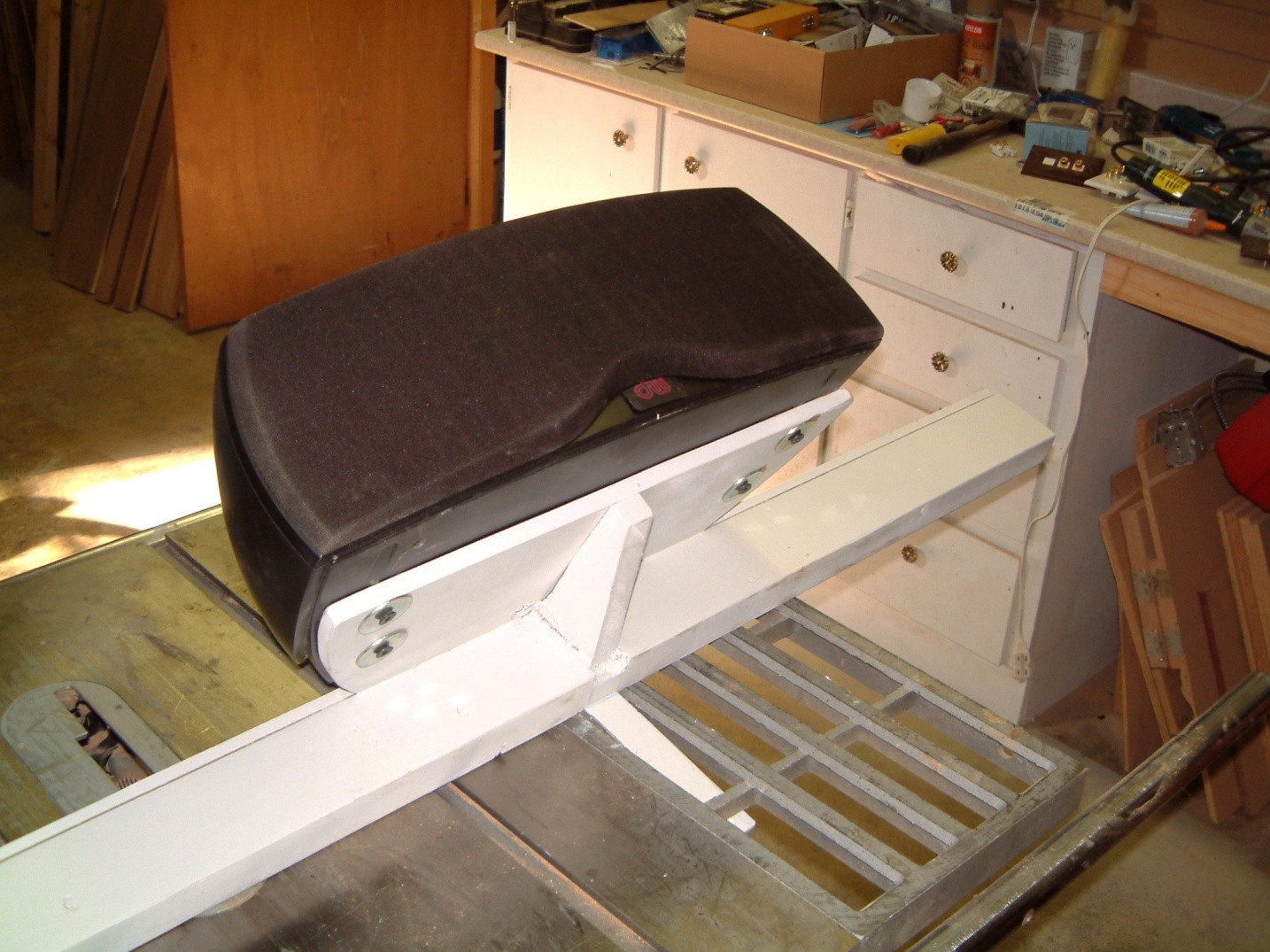
Remember that this wall is heavily padded. The 2" x 6" fir studs had been extended with 1" x 2" pine strips as the fir was too dense to accept staples! The mount had to 4 feet wide with a vertical steel bar that could be screwed to the 1" x 2" strapping at the center line of the room.
A problem might arise then the room is in a basement. The ceiling might have been lowered by using offset mounts for the drywall ceiling. Where there is not enough space for even a three inch layer of high density sound insulation - where the air conditioning and or heating ducting - not to mention wiring of all sorts - this is something to consider if you have to apply for a building permit.
Unfortunately, the room is a bit dark to show the center speaker and its mounting as the mount was sprayed with flat black, so there it is.
You will see that I had to add another horizontal 1" x 2" to anchor the bottom strap which had to be bent to lie flush with the outer surface of the 1" x 2". The screen will cover it when its pulled down. But, the added fiberglass behind the speakers was a tittle to thick for a stable mount. I had to add four 1" x 2" x 7"'s as 'shims' to move the center unit forward about 7/8".
I then screwed the speaker to the mount using four 1/4" x 20 allen screws with the 1 1/2" washers to allow easy adjustment. I realize that the stucco'd surface on the ceiling is a bit mottled, I hadn't added the felt pad when I snapped the photo. I had to let the speaker wire dangle since the wiring connecting the plate up on the wall to the right of the speakers was severed when the sprinkler head was installed. I did fish a bit until I realized that the wire was stapled to the side of the rafter and I would have to move several ESL interface units (XIM -11a's) to access the severed wire. Oh well, this can wait to another time.
The screen mountings were 127 1/2 " from end to end; therefore I had to suspended the screen by first using a pair of 1' x 1" square heavy structural steel pieces running across two rafters. I used 6" lag bolts at each end to secure them to the rafters. To make sure that I centered the lag screw on the center-line of the rafters, I used a Tichner drill to open the ceiling dry-wall at each position of a lag-bolt. These rectangular steel pieces run from the front wall (the screen end) well across the first rafter after the wall. There are rings at the lower ends of the 3" long bolts. I used a pair of lock-nuts at the upper end. I drilled and tapped the holes for the ring bolts and used Locktite (tm) to secure them in the 1" x 1" structural steel pieces. I was lucky as I found several molded plastic caps to hammer into the open ends. The screen itself is attached to plastic covered chain to stop rattles.
Lateral location of the screen presented a possible problem as the side walls are padded - as is the wall behind the screen itself. I had located the center speaker system by locating its support on two vertical battens four feet apart - on the exact centerline of the room. This was in 1982 when the room was being built. I decided to use a plumb line referencing it to the tab used to pull the screen down. You can barely see this tab just below the white frame of the screen housing.

This places the plane of the screen about 4" from the padded surface of the wall. The center speaker mounting is forward about seven inches (away) from the surface of the projection screen. Therefore, phase coherence is maintained, as the left and right (front) speakers are at each side of the room, well away from the vertical pieces of wood in each side of the room. Drawing an arc from all three sets of speakers was very informative; we had to move the left/right speakers forward less than three inches to achieve phase coherence at a pass-band from 2,500 Hz down to 200 Hz. The left and right speakers are free of the vertical wood trim which masks each end of the (side) retractable (split) curtain. The screen itself is masked for about 5 1/2" by its supporting housing. Thus, the centerline of the center speakers are about 10" above the upper margin of the screen. As the Barko 808s will eventually hang underneath the ceiling, if it is too close to the ceiling (so that people don't hit their heads). it might mask the upper part of the screen. It has to be a compromise; trading vertical size against the rear seat obstruction caused by the people sitting in the front row chairs. Screaming "down in front" seems cheap!
The center split curtain itself is attached to/and hung at each end from a hook in the curtain housing. The screen's housing just clears the center speakers. On the first setup, I realized that the use of turnbuckles at each end left the screen much too low. I then used chain, as is used for eight foot fluorescent lights. I was able to use an extra length as a safety chain. In this photo, the screen is about 7 inches too low; and thus needs to be raised to where it is only about a half inch below the mounting for the center speaker array. I still have to apply a dull black self-adhesive MacTac to to hide the roller housing for the screen!.
As intended, I placed the two sub-woofer cabinets on their sides; I placed them facing the wall with a two-inch clearance. This loads the sub-woofers two ways, they are in the angle between the floor and (well padded) wall. There is the acoustic loading from the proximity to the wall. As these cabinets are heavy and lie on padded carpet on a concrete floor, there is no structural feedback. Even with subsonic bass, the curtain does not move - we attribute this to the lack of coupling between the four rear facing sub-woofers and the curtain. They just clear the inside corners of the left and right speaker array.
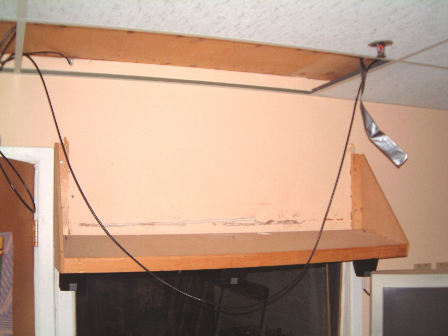
Sometimes, the fickle finger of fate lends an unexpected hand. We had a unbelievable thunderstorm the third week of July. It took out the air-conditioning fan when the contactor failed. The thunder was so bad, that the roof was shaking. Even though all our computers are on UPS's we had to shut everything off. A tornado funnel touched down six blocks east of us well after we shut down about 2:30 PM. We came back on Sunday to find that the cantilevered shelf that held the 17" monitor, had torn away from the outer wall of the sound room. It fell onto the floor in stages, it first landed on the table that the mixers were normally on; but, they had been moved to install some connectors. Then, it slid off the table where it struck the back of a small ladder which in tipping away, allowed the monitor to fall onto a tangle of cables. It never struck the concrete floor!
Well, I found why the bracket failed. On the left end, it was nailed to a single stud. The right end had been nailed to the 5/8" drywall. The thunderstorm allowed the spiral nails to pull out.
I added a 17 1/2" (width) piece to the back offsetting it several inches more to clear the right speaker. This time I used four lag-screws at each end. I wanted to re-use the bracket so I trimmed two inches off the bottom, used a belt sander to clean off the back, glued and screwed it to the extension plate. I epoxied the angle bracket in place.
I had to trim off some of the shelf as well, it's amazing what a SawsAll can do!
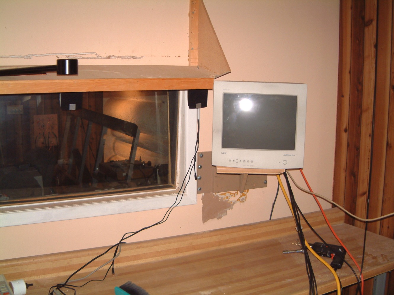
The photo is a bit deceiving; the extension to wall bracket is on the left side. The monitor is only two inches off center. You can see where it tore off the drywall. I had to raise it three inches, so that's why the older - wider shelf had to have it's right end trimmed.
I got an unexpected shock as well, when I realized that there was no reinforcement under the counter! I was about to stand on it, then it struck me why it was easy to clamp on the under-the-counter keyboard and mouse pad. I cut a 2" x 4" as close to the metal legs as I could; then glued it up under the counter so that it cleared the supports for the keyboard. (Of coarse I mounted it with its cross section vertically aligned. I used #10 x 3" tough steel drywall screws on 7" centers to anchor the edge-on piece of 2" x 4". As there was a length of oak 2" x 2" at the back of the counter so long as I don't stand up dead center, it will be OK (I hope).
In the process, I wanted to check out the monitor by using a wide-bandpass device that will operate several monitors in parallel. It has the advantage that the connection cable (for each monitor) can be over a hundred feet in length. Sixty meters gives the -3 dB point. By setting the Barco's Peaking to the highest amount, the image on a DVD is very crisp with no ghosting or ringing. There is a four-way splitter that is able to drive two-hundred foot long cables with a -3 dB rolloff at 200 ft. Using shorter cables (16 ft - only 0.30 dB) makes it ideal.
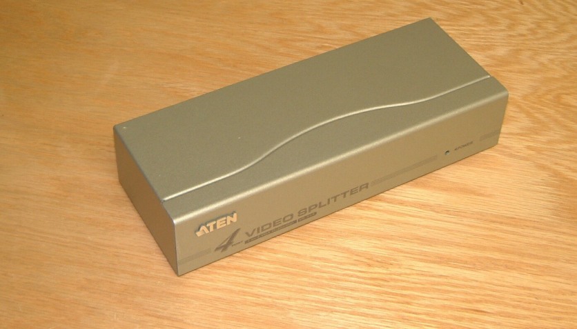

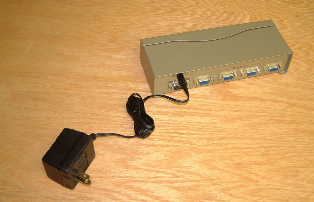
The small box, is ATEN Video Splitter # VS94A - it has a plug in supply. Be forewarned that you will need a double-female adapter for the input. There is one made by TechCraft (VGA MINI GENDER CHANGER - #GCMVGAF) but it has a minor drawback - the double nuts at both ends have to be unscrewed so that this device can be plugged in! This photo shows that it does work. I also checked it out using a sixty foot length of VGA monitor cable. I couldn't discern any difference. I still remember the absolute look of horror on the salesman's face when I bought that much cable. Well, he had it in stock didn't he?
I planned to relocate my preamp next to the computer even though it is at far side of the room, however, on a second thought; it would take up too much space. So, the record bin stays where it is! The vacuum SOTA turntable will be transferred to a new granite slab. I realized that I could mount a vertical double row of XLR connectors next to the double door; this seems a simple solution as I can use a horizontal plastic bushing as is used to pass fan-fold computer paper though a table. I can flag the cables on the connectors at the other end where they can plug into the mixer. With this change came the thought that it might even allow me to place several chairs at the rear of the room.
I shouldn't complain when a new thought occurs and I have to make another alteration or add some other "essential" bit; however there does seem to be an almost endless amount of work remaining. Does work always grow to exceed the time available?
There was another
thing I had delayed for several years. I had two double magnet Focal mid-range
drivers that were waiting installation. In 1989 spent over a month testing
cabinets to optimize the crossover designs. I even went as far as building a
four driver crossover to use with the double magnet drivers. This
assortment of drivers - however these drivers had not been installed in
the finally finished cabinet There always seemed to be something more
urgent! I cannot believe that it took me over three years to clean out the accumulated
junk of ten years of "The Dayton Wright Group Ltd." Remember that I
had to clean out the front offices of The Dayton Wright Group Ltd., stripping
them down to the floor, repainting everything, laying carpeting, building
benches and cabinets, before we could move D. W. Electrochemicals Ltd. from the
Leslie street address. Then it took four years to construct and wire the plant
- all the while continuing the production of product. I still have more work to
do, but I finally created the space to assemble everything into a pair of
speakers!
As soon as I can move them into the sound/media room I will have time, I hope, to finally move Max's console out! I have been waiting for nine years - with a succession of people waiting to buy this "now classic western design"!
As some of you
have e-mailed me, my last update on room construction has been delayed for over
two months. Here's the reason. I have had recurring problems for three years.
First, my ISP changed their uploading method. They changed from HMTL to
SHMTL for "security". Most of this web-site had to be reloaded.
Then, their servers were moved to another location. No problem, I
"enjoyed" spending three days tracking down missing pictures. Then my
best laid plans ground to an abrupt halt when my ASIS P2L97-S motherboard
failed.
I should have anticipated this when the onboard SCSI connection ceased to function. So I bought an Adaptec 2096 card and disabled the SCSI connection in the Bios. This was OK for a while until my HP SCSI scanner began having problems. I went on coping as best as I could. My printer went down next and as my Iomega 250 Mb backup drive was connected to the printer port it didn't work. So I bought an Epson Stylus C80 and connected it to the USB port.
This operated very well - for a time. Then some of the AC receptacles seem to become erratic. So I switched to a different outlet. That seemed to stop the problem for about two months. I swished to a higher capacity UPS as well. I have has too much experience with "switching-mode" power supply's failing, because the electrolytic capacitors don't operate at the high frequencies demanded by "switching-mode" supplies, the capacitors have a tendency to develop increasing resistance with the passage of time. This is apparent when the voltage power supply on the computer started to fail. The "regulated" output voltage was about 20% lower than it should have been.
So, take the obvious step and buy a high priced and larger power supply with an extra cooling fan. The regulated voltage now was normal. Everything seemed OK.
I have got into he habit of ensuring that my virus protection is OK - I use
Norton 2002 to ensure that when I connect to the internet it loads the
latest version, It checks my incoming and outgoing e-mail as well. I have got
into the habit of "imaging" all my files, especially after
"defragging" them. So, I was surprised when I was interrupted about
six weeks ago. My "Lab" computer wouldn't restart. The optical mouse
light didn't go on. The keyboard light flashed and I heard the two beeps of a
keyboard error. The screen stayed blank. That's OK if the screen saver is
operating as it needs a mouse motion to resume
normal screen operation.
Could it be a virus - such as a one that saves key-strokes to a "hidden file" - to be accessed by someone else when your computer is on the internet? We are protected against access by software that alerts you whenever someone attempts to access your computer by any port whatsoever.
OK - it had to be a case of progressive delamination of the motherboard. I have
experience of this when we had four layer boards made for us when we were doing
R?D on a large preamplifier circuit board. We had a carefully designed ground
plane as layer two. We had six prototypes made for us. They were all wired the
same way, but three of them
oscillated. Nothing I could do
worked. We tested two of the boards for open internal traces. We found five on
board "A", seven on board "B" and two on board
"3". Then we went to a more expensive contractor to have exact duplicate
PC boards manufactured.
Ths time all of the boards worked perfectly!
But I also found that some of the ground-plane shielding was ineffective. My conclusion? The previous boards had delaminated.
So, it was necessary to switch motherboards. I had been using a 333 Mhz Pentium !! with an ASUS P2L97-S AGP motherboard had an Intel chipset.
I remember contacting ASUS, well after the Pentium III's came out. I was advised to switch to an ASUA TUSL2-C motherboard, as it compatible with the other Intel chipset. Great! I had been anticipating this problem and had already bought this mother board. But, in the process of reorganizing the "stacks" - the stock storage area in the rear of our plant, this motherboard was moved. I spent two weeks attempting to locate it. Hopeless.
So I ordered one. But my supplier sent me one with a VIA chipset - in error. He told me that board was no longer in stock. It struck me as a bit strange. Again I contacted ASUS, and was told the same thing. I wondered - why would ASUS advise me to use this board? I shopped around and found that another ASUS dealer could get the correct board. I ordered it and put a "hold" on the job. I decided to use a "mobile carrier" for the "second hard drive as it carried most of the various web-sites I have written. Even though I sad used an IOMEGA Zip drive for backup it was difficult to retrieve these disks from my safe deposit box. The "removable" drive is at the lower center of the photo. But the technician found that he could "adapt" the VIA chipset easier than he thought. So there wasn't any problem after all!
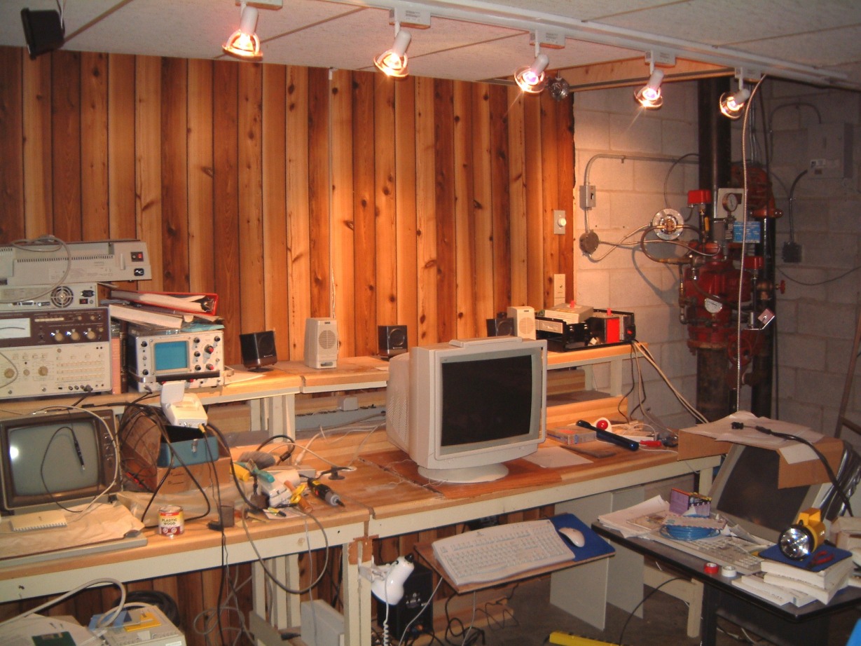
To see the first rail lighting look at these - the rails are not connected yet!

Ok. Problem solved. Or so I thought.
Meanwhile, I gave it more thought - the "lab floor" was a mess with a tangle of wires. The eight foot fluorescent fixture was too bright - and I had to take down some of the "suspended ceiling" panels to run new wiring - audio, telephone, DSL and LAN. It was time for a major rewiring -etc.! As you can see in these photos, I actually had to clean off the upper level of my bench in my "lab". I think that can use the "Sawsall" to notch the upper shelf to clear the back of the 19" monitor - enough to move it back five inches. I had an old (and HEAVY) keyboard slide that will allow the keyboard (and mouse) to be slit underneath the bench. OK, that's common. But, this mount has other advantages. It allows the keyboard to tilt back up to 25 degrees; it can be moved both up and down and sideways as needed. This is why it's steel frame is so heavy! I bought several of them in 1987; using two of them as their installation needed two people and at least seven hands. As they were manufactured in Germany the "complete" instructions were in German. As I had a smattering of technical German. I knew that if there wasn't any current usage word (noun) to call an item, they'd make up a new word from several nouns that "almost" fit, and go on from there! There were abbreviated instructions in several other languages; most too short to decipher. After several hours of sawing up 4" x 6"'s, I finally got it installed. However, I had to bolt the thing in place by using 1/4" x 20 pan-head machine screws (you probably know them from IKEA). Only they cleared the mechanism of the frame enough to allow it to work. They are great, IF you are installing them in a factory. But in the field, @^%**#. They are similar to the oil filters where you might have to pull the engine just to change the filter cartridge! But, onward!
Well, I put up an eight foot long railmounted lighting bar under the hung ceiling. Connecting it was a tedious job; as we have to employ BX wiring (for insurance reasons), all wiring has to be made under commercial standards. As I am a licensed electrician under Ontario Standards I can, if I can find the time, do all my own wiring. However, this job seemed beset with problems. First, the rail was dead. I left the source end uncovered so that I could plug it in to a receptacle. I traced the wiring thro' to the connection fixture for the rail. It was OK. But the rail was dead. OK, perhaps I had a faulty rail. I was determined to run a new rail. Only this time, I would mount the rail in a 1" x 6" - ten feet in length. Dutifully, I primed and painted the 1" x 6" (shortened to be about 11" longer than the power bar + connector. This time I pre-wired the end to connect, via a short nipple, to a right angle BX fitting, running a clear seven feet of BX to a three wire connector.
I put two fixtures on the rail and plugged it in. Nothing. I checked the end connection. It had power. I had purchased two new fixtures and the low voltage halogen bulbs they needed. I tried one. Eureka, it worked. Apparently the specs for the nine month old rail were different than the new one. I discovered (the hard way) about MINOR incompatibilities in CSA approved electrical fixtures from China. I tried several of the low voltage fixtures that I had bought a year ago. None worked. I found that "Hampton Bay is a "House Brand" of "Home Depot". Well, OK, I god burned. So I went ahead to install the rail. PROBLEM. The #@*?$% paint was reticulating as the "Pine with some tight knots ? dried wood" was wet below the surface. What to do? I considered asking the warehouse boss to come and explain why the wood was core wet; I even could demonstrate how he might help me! But, I slept on it. One solution, might be to expose the wood and use a heat lamp bar to dry it out. The alternative would be to pack the wood in silica gel for several days and, after using a "moisture meter" to ensure that it was dry, paint it again. I decided on the latter.
It took seven days to dry, then I painted the track mounting 1" x 6" for the last time. The screw-in anchors on the top were easy to use. I raided an old reel of 12 Gauge copper wire and used the six foot lengths to hoist the light bar up to the suspended ceiling.
Being cautious, now, I gave it a trial run before I connected it to the switch box. Here it is.
Now I can connect it up. These lights are a vast improvement over the eight foot long fluorescence I lived with for eighteen years. As you can see, I haven't moved the computer from out of the "back room" yet. As it gets colder, this "back" room runs about 55 degrees F. The insulation on the outside concrete wall stops three feet from where I have to sit. The problem is that Leigh in a burst of exuberance ordered eight hundred IM 10 steel cases. We repainted about a hundred for our own use - remember, we had to strip and silk screen the front panels + the cases! I know that I'll have to move them in the spring; when it gets just warm enough to complete the mezzanine extension. Then, I'll have to move the horrendous stack and insulate the rest of the wall. To put it in perspective, we were paying a gas bill of $900 per month during November, December, January, February and March (1981) with three unit heaters running to keep the working area at 68 degrees. The first thing I did was to partition off the loading dock. It changed to the carpentry shop.
When I insulated 60% of the back to the eight (and a bit) foot level, our gas bill dropped 35%. We built the sound room, and this dropped the heating bill. By 2000, our gas bill was down to 445 - $ 500 per month during the winters, and we had shut down two unit heaters!
I have spent two days in sorting out the profusion of wiring connecting this computer - to its side, rests an old '486 computer running Win 3.1. It hasn't crashed in nine years. On it, I keep notes on programs I am sorting out. As it has a nineteen inch screen, I can turn to it and refer to my notes. To me, it works much better than any "Palm Pilot" - I can see the screen at a glance. You can just see it at the lower right of the photo.
I used lots of duct tape to insure that I couldn't trip over anything when this room was dark. You see, it was so crowded before, that I had to be extra careful to avoid banging into anything; I got into the habit of switching on the lights before entering. But now, with all the extra vacant floor space (and the dimmer control on the wall behind the computers), I feel lost!
The next improvement, was the installation of two hanging folding doors across the "stack" opening. In the winter time, the cold air, descends from above via the stack opening, and those it is rare that the lab area is more than 60 degrees F. On days when the outside temperature is -15 degrees F, it gets even colder as the concrete block wall can not be insulated in the stack area! The solution lay in two hanging and folding doors. I had to use two 5/8" thick medium-density hardboard to make two partitions so that an 80" high folding door could fit. The actual 80" allows for a track that the folding doors hang from. The track is taped up on the underside of the opening while the wood screws that support the track are positioned. The one person installation of these things that form an 80" opening was a bit tricky. First I cut two pieces of 1" x 2" four feet long, attaching some blocks at the top as hangers, and another two below to support the hanging piece, I used a series of 1 1/4' drywall screws approx. 8" on centers, (predrilling and countersinking before placing the first section - the shorter one) in place. I followed this by a piece of 1" x 2"on the inside. As I did not have much space in which to work it was mildly difficult. Therefore, I decided to fabricate a fixture that I would attach to the short unit with drywall screws. This way, (I hoped) I could lower the longer (and heavier) one into place. I precut an 80" piece of 1" x 2" to prop up the free end (next to the west wall). The jig had a retainer so that the medium density whatever could not slip off with another angled piece on the inside for the same reason.
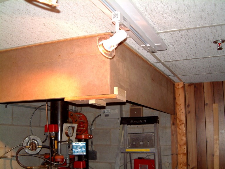
The jig worked very well. I was able to level it jus' fine. I glued another piece of 1" x 2" on the inside to support the track. I found that anybody who installs alarm or phone lines picks whatever is the nearest wooden piece, to staple whatever wires that are needed for a speedy job. I have found phone wires on the surface of baseboard, under the sharp edges of the metal rail used when installing a dropped ceiling; and now I have got used to chasing down shorted phone lines by tracking each time to see where someone didn't thing to look. I gave repaired 90% of breaks this way.
I kept delaying the needed assembly of the remaining extensions; something was bugging me after I unpacked them from their carton.
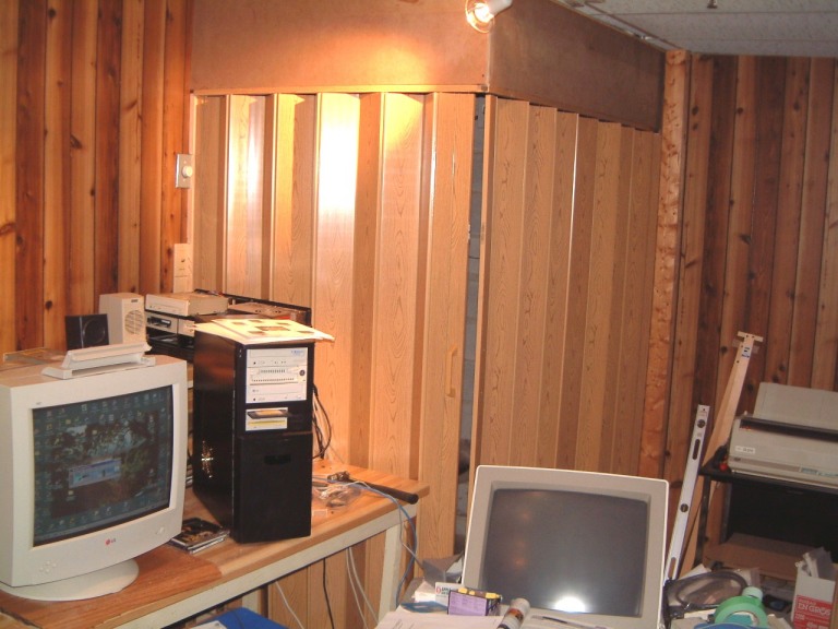
After sweating over the addition or 48" to a nominal 30" wide door (one if the 8" extension panels had been returned as the idiot had removed three 4" sections and had reassembled a single 8" section with the #*@# hanger at the bottom so that he could use a four inch section by itself; this cannot work! I spent several hours attempting to slide an eight inch (four inch - when folded) section together before I realized what was wrong. I purchased two 32" sections plus a bunch of 8" extensions in the spring of 1999. Then they sat in the back of our plant until I could find the time to assemble them.
Finally, the double set of folding and hanging screen is installed. I used a quarter round at the corner and applied epoxy on one door stop - the one on the visible corner. The longer door has a magnetic catch. When I am away In winter time, I'll leave these doors wide open to make sure there id access to the sprinkler stack. With these doors shut there isn't any draft along the floor as there used to be!
I have been delaying the 'computer lab' update far too long. After I got the Pentium 3 computer working by replacing the memory sticks with Kingston Memory the 'Dreaded Blue Screen of Death' hasn't occurred in a week. ( It used to occur two or three times a day). The former tech blamed it on having too many programs installed. Pardon me, my computer is used as a tool, I maintain it properly, don't install programs that haven't been reviewed properly, use 'Search and Destroy' to look for 'bots' that act like maggots in any computer that they infest. I use an automatic update (not Microsoft's) on my firewall and virus 'traps'.
Therefore, I resent any technician that tries to palm me off with used to be termed 'Ma Bell's Excuses and Lies'.
Back to the changes in the computer lab. But I must make it clear that I have a well lit 'back room' where I do most of the computer assembly - nothing (well, almost nothing) from the East gets moved up to the western 'computer Lab' until it functions correctly.
Here are a couple of shots. The left is the monitor connected to a switch (the screen shows a duplicate of the main computer screen.
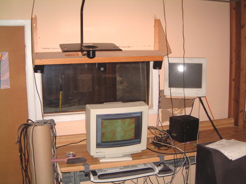
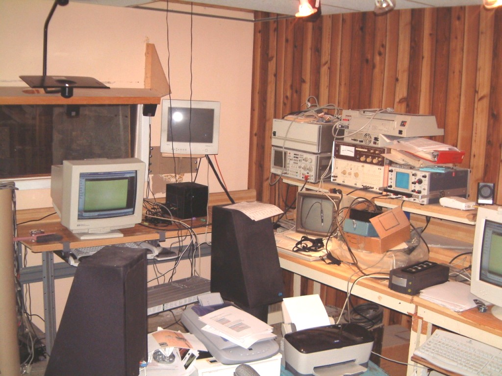
When the Pentium 4 Windows XP is operating, I'll take another photo.
Amazing! On June 14th 2004, I found enough time to move the Pentium 4 with Win XT pro, to the east side of the computer lab. As the photo shows, I decided to set it up on the table where I will locate the mixers. That way, I can still fiddle around to 'tune-up' the setup before I have to lift the large monitor to it's final resting place.
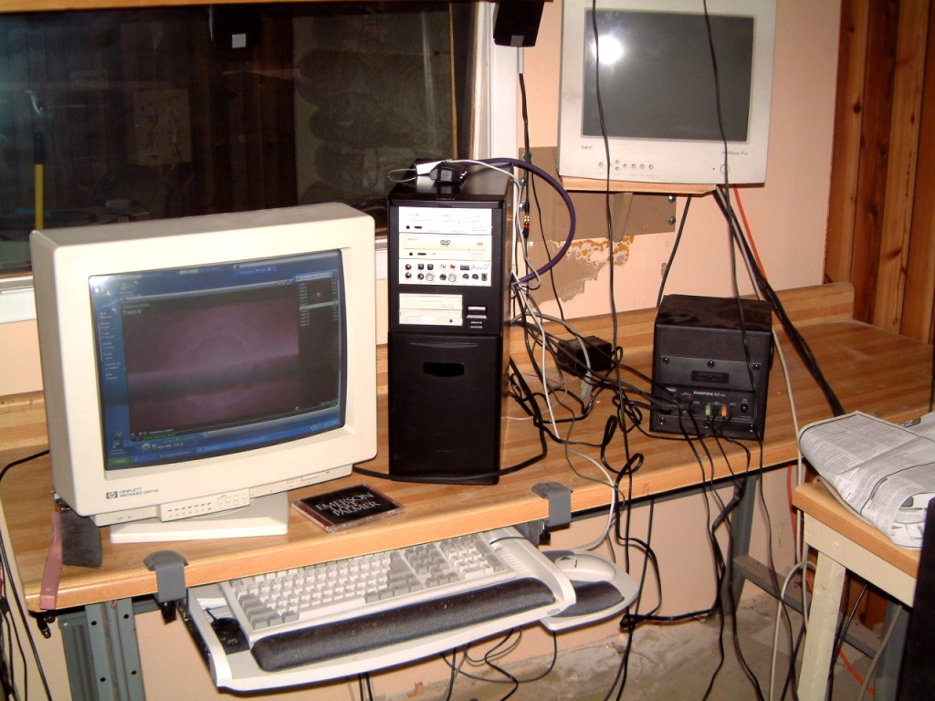 As you can
observe, the wiring is a bit of a tangle. Why do long wires have a tendency to
re-route themselves. I propose a new law 'The More Complex Any Wiring
Becomes and the Longer The Fixed Length of Any Wire That Must be Crammed into a
Small Area. 'The Tangle Factor' increases as the fourth power of the length of
the longest wire in the set! Will there ever be a set of cables of any
kind where the length of the wire is two to four inches longer than what is
needed? Probably not!
As you can
observe, the wiring is a bit of a tangle. Why do long wires have a tendency to
re-route themselves. I propose a new law 'The More Complex Any Wiring
Becomes and the Longer The Fixed Length of Any Wire That Must be Crammed into a
Small Area. 'The Tangle Factor' increases as the fourth power of the length of
the longest wire in the set! Will there ever be a set of cables of any
kind where the length of the wire is two to four inches longer than what is
needed? Probably not!
I dislike (for
good reasons), placing the LAN connector close to the telephone jack, at least
on the same plate. Therefore, I never "bundle" the two sets of cables
together even though its neater. I have found that it helps to have an RF
bypass on a phone line carrying a DSL signal. One thing that nobody mentions is
that a DSL signal has a range limit. Too long a line carrying a DSL signal and
the less the reliability and speed of the connection.
I know what it states in the handbook about the height of the wall plates (48"), but often when placed at that height, there might be a problem. Often, nobody can climb around a computer desk or table to reach the two jacks (at least without a post-plug-in visit to the chiropractor).
Just when I thought that my new office computer was working perfectly, it froze! First it was set up using only one drive (45 Gig - Drive C). I had a copy of Partition Magic Ver 7 that I trusted, so I used it (first backing Drive C - 182 Meg - using my Iomega Zip drive). Then I attempted to partition it into five drives, Drive C, would be 18 Gig with the other drives proportioned accordingly. Part way through the computer decided (on its own, that it didn't like it's being separated from it's other other drives, It seemed to be developing a mind of its own as it was it resisting. Maybe it did not being thought of as having multiple personalities! It shut itself off! I suppose somewhere in the minds of "programmers" at Microsoft, there may be a "patch" that can fix this aberration, however, nobody I know of, can find it.
The nerve! it took two days to the technician to get it on its "feet" again. Even though the output connectors for the speakers had been disconnected and the power supply for the amplifier had been unplugged at the duplex receptacle, it made no difference for when the speakers were connected again, I found that the sound card would not work on the two front speakers.
February 2003 - Below, is a photo of my "inner" office (where my desk can be a mess without offending visitors). I replaced the older four channel Cambridge Soundworks FPS 2000 Digital system with the Creative Inspire 5.1 Digital 5700 speaker system. But it was the sound card after all. It made now difference.
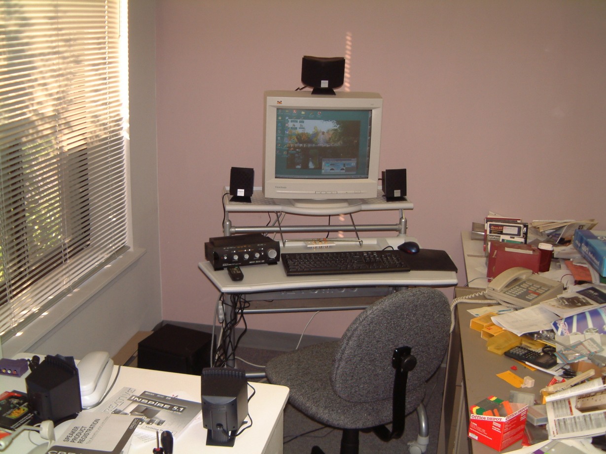
After I has the sound working properly, I had to clear the other table (where I had installed the computer) to make room for the large format HP Printer. As I needed the space, I had to installed a set of rear speakers high up on the rear wall of my office. But this had to be delayed until I ran the LAN cable as I wanted to make sure that it worked. I had to connect the "source" via a four connection plate behind my computer "desk", then fish the wiring overhead (over the false ceiling); and run the two sets of wires to two sets of jacks behind the speakers, as shown below.
Note that only one speaker is shown. As these units have a tapered base, to use Velcro (TM) to hold them in place, I resorted to using wedge inserts on the bottoms and then using Velcro (TM) on both the wooden wedge as well as on the swivel mounts (the black waveforms screwed on the room wall).

To continue, again, I purchased an upgrade from the older (defective) sound card to the SB0090P Platinum.
. After several additional 'fixes", "perhaps" it was tracked down to the DOS part of Norton 2002. When it was 'remmed out', the computer seemed to operate properly substituting "scandisk" for Norton. We will have to wait and see. I still believe it's the power supply's electrolytic capacitors. More to come!
By the way, the control and amplifier unit can drive you to distraction as there are so many possible settings. I resorted to taking a shot for each use. Since that was done, I can refer to the settings for each one. I have found that some DVD's will bring up a warning "not supported", but they can be played.
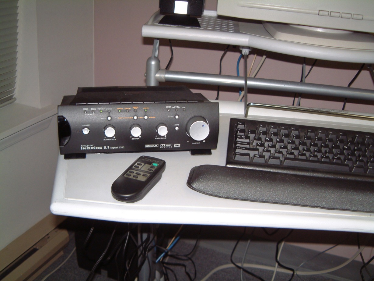
It took too much time to set it up, and I hate to say it, but the "24 bit" player preforms extremely well on the DVD's and CD's that support it.
I think its about time that I switch to DSL. I have been installing LAN cabling in our plant, I have a LAN hub already installed. But, I think its about time to build another computer to act as a dedicated server. I have four 80 Gig hard drives and a smaller one with Win 98 already installed. I bought the Promise 2000 RAID card some time ago, but I've been too busy to assemble anything.
I took several
days off to rig up a friends house for Halloween. Its far enough away from our
plant so that I am not inclined to drive down. With some R?R, I found enough
time to begin the server. I bought a new case from "Magic" that had
enough front-panel-accessible slots (I need cooling for all four drives as they
will be running so long as the server is on). I located some fans by "AOC
TM " - model UHDC. The heat sinks are extruded aluminum and are
spring-clamped to the top of each drive. Each cooler has two 4 cm fans; the air
is sucked in at the front and exhausts into the case itself. I used a two fan
power supply (one draws air from outside and the other bottom mounted fan
directs the flow down into the case itself. There is another exhaust fan inside
the the rear - and the case itself has a large fan mounted on its side as well
as a corresponding vent on the other side.

But, it wasn't until I removed it from the carton that I realized that the mother board and rear panel assembly were an integral part of the case itself! Then, I soon found that the plastic "carriers" for the hard disk drives took up so much space that there wasn't any way I could instal fans. The case met enough of the "speck" so I was able to discard the "carriers". The case had another problem; the motherboard had to be installed by the use of square plastic inserts with a self-tapping screw. I found it easier to cut threads in the plastic and use standard screws to instal the motherboard. But, the motherboard was "grounded" by a metal spring clip insert. Uncool! l soldered the %#*?# clip in place. In the next photo, you can see the square mounting holes for the motherboard.
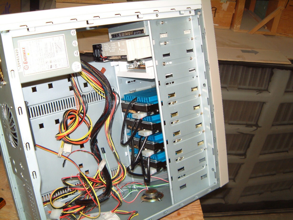
I decided to use round Ultra DMA cables to minimize the "can't see" problem with the flat cables. I'm sure that anyone who has assembled or serviced a computer will know what I mean!
Two days later, I
spotted some spelling errors. The problem is that I have spent so much time in
programming, writing and editing, that my eyes are irritating me, I change my
glasses at least once a year. However, twelve years ago, I developed cataracts
(from exposure to DSMO at MIT). The surgeon that operated, didn't seem to
understand that my right eye is 2.2 MM higher than my left eye. Prism
correction does not work as it only allows both eyes to achieve non overlapping
images at one distance. With trifocals it is worse as the right eye is looking
through the close-vision part of the lens while the left eye is using the
second part of the lens (used for longer vision). The result is a weird type of
false stereo where objects seem to be further away than they are. I try to
write with my pen about one and a half inches above the surface of the paper as
that is where I see it. It took me eight years until I was able to convince an
optician to make me glasses where the right set of lenses is 2.2 MM higher than
the left eye. He was astonished to find that I did not need wedges after all.
Still, it will take several years to overcome ten years of bad prescriptions. I
wonder how many other sets of glasses have the same problem.
I am fortunate as I used AutoCad with a rendering software that allowed ray tracing. Using this allowed me to set up several hypothetical cases where I could simulate several sets of glasses to discern whether 2.2 MM was correct.
Now back to the
server. The motherboard fit the case with the mounting screws lining up
exactly. I remember that it was rare that computer cases were produced to meet
a specification; wracking of the case was common, and the sheet metal was razor
sharp at the edges. Currently, most (not all) cases fit! There are more cases
that use heavier gauges of aluminum for the case shell.
Here is the server as it looks at present.
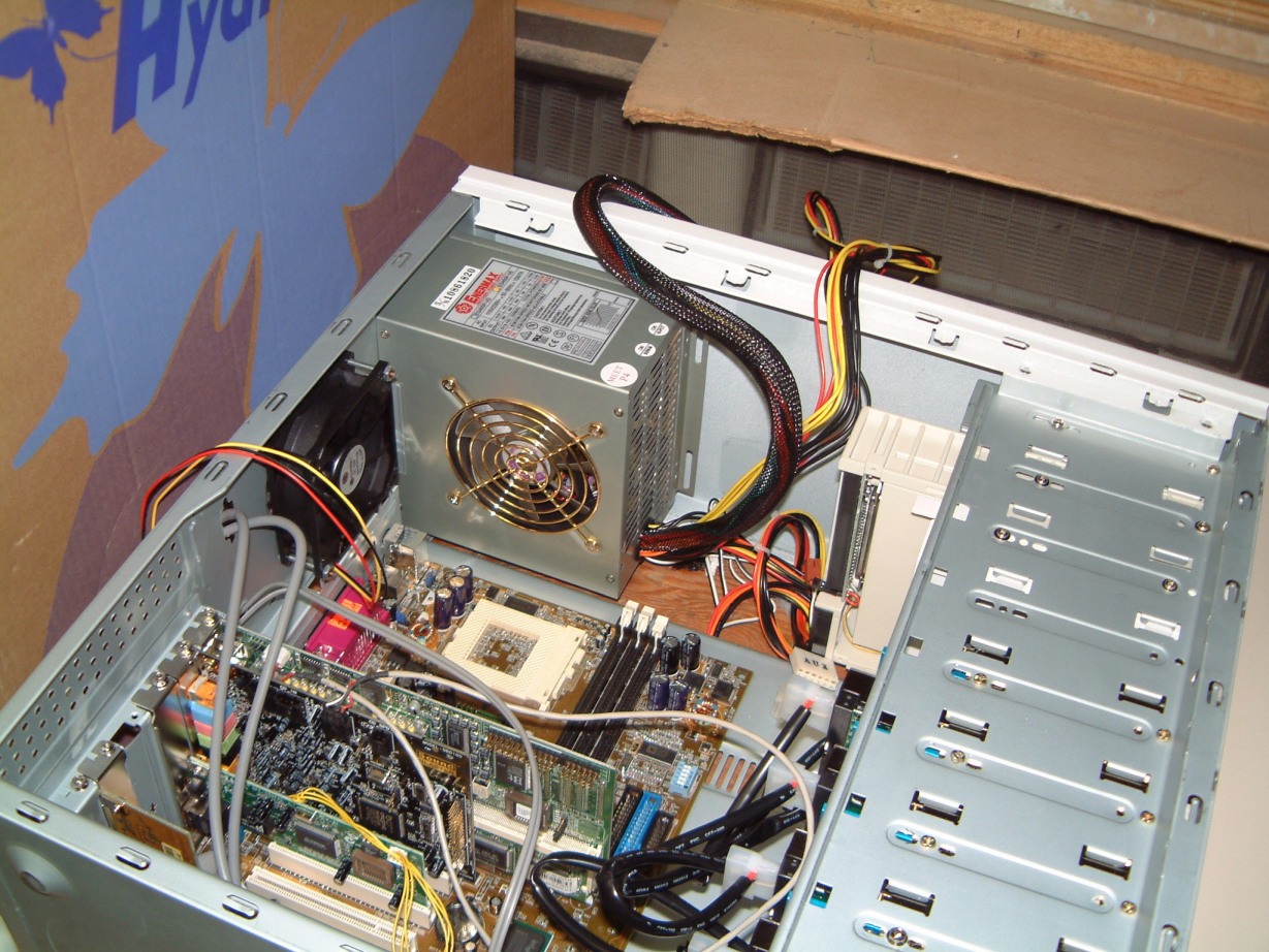
However, I seemed
to have a recurrent problem with LAN cable connectors. Terminal five is at the
rear of the "block" of the connector. It seems vulnerable to being
damaged by the push-down tool ( I use a cable checker all the time). It showed
that there was a wire 5 break on one of the CAT 5e connectors. Even though I've
checked both ends several times and have been using a BIX pushdown tool for
more years than I care to remember, this still bugs me. I will have to cut the
LAN cable and attach new connectors to both ends.
Good news, several months ago, I ordered S-Video connectors for the Leviton (TM) wall plates, and they just arrived! OUCH, they really cost!
I dislike spending so much time on computer stuff rather than on sound and
media. However, with 24 bit encoding now becoming more available, I cannot duck
it anymore.
Well, as I have been postponing the alterations to the media/sound room for too long, it finally got to me. I wish to run a deep cove around three sides of the room. (starting at the vertical piece that hides the edge of the open curtain), then along the rear wall, and across to other side wall. I plan to use "rope lights" in the cove's recess. This way, I can have a dimly lit band of illumination on three sides of the room. I already have remotely controlled dimmer to replace the present SCR dimmers. This way, I can use the BARCO controlled from inside the room, or from outside. I have two computers, one inside, the other outside. The wiring is in place so that the BARCO can be run from either location.
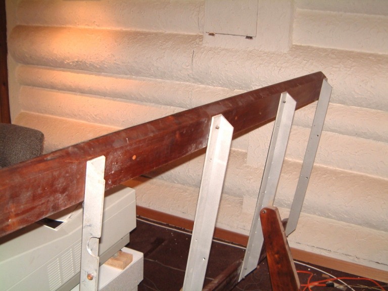
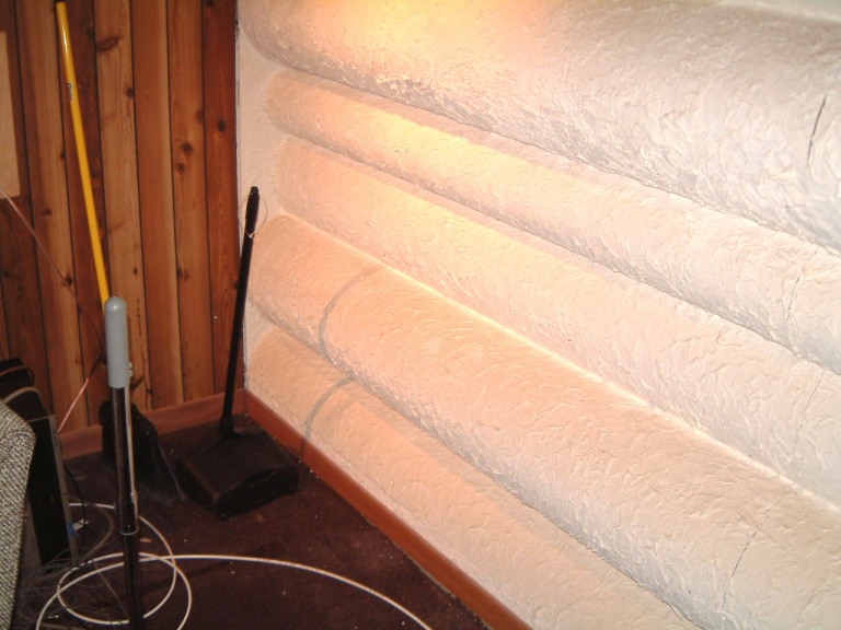
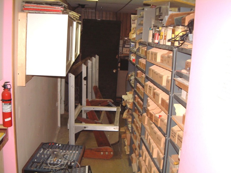
The left photo shows Max's Black Walnut Console (Less the granite turntable base), when I had just moved it out from the rear wall. The middle shot is the dirty wall itself. The right picture was taken just after I replaced the hinge pins on the door. It took me several days to remember just how I managed to move it (myself) into the room after my staff had left for the weekend. In anticipation of eventually having move it out from the room, (again, by myself), I spent a week in measuring things. Then I made supports to locate the IKEA cabinets off the floor to ease their installation. I used the same supports in the hallway. So Max's console cleared the IKEA units by a full inch. I will build an elevated floor across the rear of the room allowing it to clear the long record bin by about twenty four inches. (Real soon now!).
Here is another
photo of Max's SSW (Supported Sound Surface) "console". Max had a
customers own equipment installed when he took he photograph. The
following is was taken from his brochure:
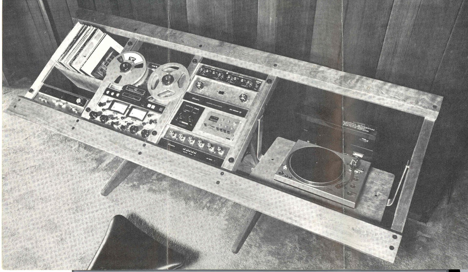 MAX GOTSCHALK
Supported Sound
Surface SSSW
A special rack for supporting phono turntables, a tape recorder, pre-amps,
power amps, switching equipment, etc. The angle of the panels can be adjusted.
The deluxe model has infinite angle adjustment and parallelogram turntable
leveling as well as shade dust protector.
An accessory clamp-on caster assembly is available as well as a clamp-on light. The unit is 96 inches long with an average height of 30 inches. The system is made of natural finish aluminum angle, steel box members and wooden rails. A wooded legged version is also available.
We purchased Max's prototype. This used a green granite slab as the turntable base (about 75 pounds). Some of the details were simplified on the production models. One of our SPS preamp's is to the right of the Crown Tape Recorder.
He was, and still is, in the forefront of design. He was noted for his combinations of different metal elements with natural materials such as leather.
Max moved to California where now resides. In his '90's, he is still in the
business of design.
Because of my decision to switch the sound card from 5.1 to 6.1, the ambiance speakers had to be located on the sidewalls of the room. Then I could selectively alter the two ambiance speakers on each sidewall of the room for balance (I thought that the speakers closer to the middle of the sidewall might be a bit too loud in relation to the sidewall speakers further back. (When I changed once more to 7.1 the two rear speakers would be stereo ambiance).
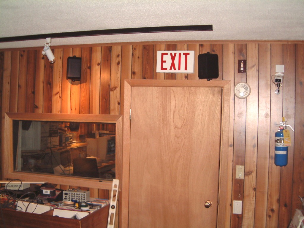 I replaced the Creative Labs Live sound card with an Audigy Platinum II, card
and I'm considering the new Hercules 7.1 card. However I will defer this until
I get the under-the-rear-platform sub-woofers installed.
I replaced the Creative Labs Live sound card with an Audigy Platinum II, card
and I'm considering the new Hercules 7.1 card. However I will defer this until
I get the under-the-rear-platform sub-woofers installed.
I finally bought
the Platinum Audigy 2 - ZS so now I have no excuse for the postponement of the
Media Room!
I abandoned the use of the Creative Labs Live sound card or rather relegated it to be used with Microsoft's Flight Simulator 2002 Pro with the console below. I'm investigating the use of two more monitors to increase the view field to both sides..
 For my initial use of the NT systems stuff (as in this picture) I bought a
twenty two inch monitor and equipped the pilots seat with an eight inch
sub-woofer at the side. I used a pair of five inch ambiance speakers. This
control column and pedals cannot be used with any force-feedback system (yet).
I used to use a plastic case in the Stabilant exhibition at Trade Shows. But,
by 1990, there wasn't enough time left to manufacture, bottle and marked the
stuff.
For my initial use of the NT systems stuff (as in this picture) I bought a
twenty two inch monitor and equipped the pilots seat with an eight inch
sub-woofer at the side. I used a pair of five inch ambiance speakers. This
control column and pedals cannot be used with any force-feedback system (yet).
I used to use a plastic case in the Stabilant exhibition at Trade Shows. But,
by 1990, there wasn't enough time left to manufacture, bottle and marked the
stuff.
Since I placed the flight simulator on my web-site, numerous visitors have asked me for the manufacture's name. Unfortunately, he stopped production in 2003, selling off the remaining stock.
I had to update a eprom and a controller chip. As the case for the flight simulator was built into a break-down 'cabinet' on castors so that I could transport it to trade shows, I had to partly disassemble it. I took the time to add several pass-thro' bushings and several tie-wraps to attempt to make it neater. Here are several shots of the thing.
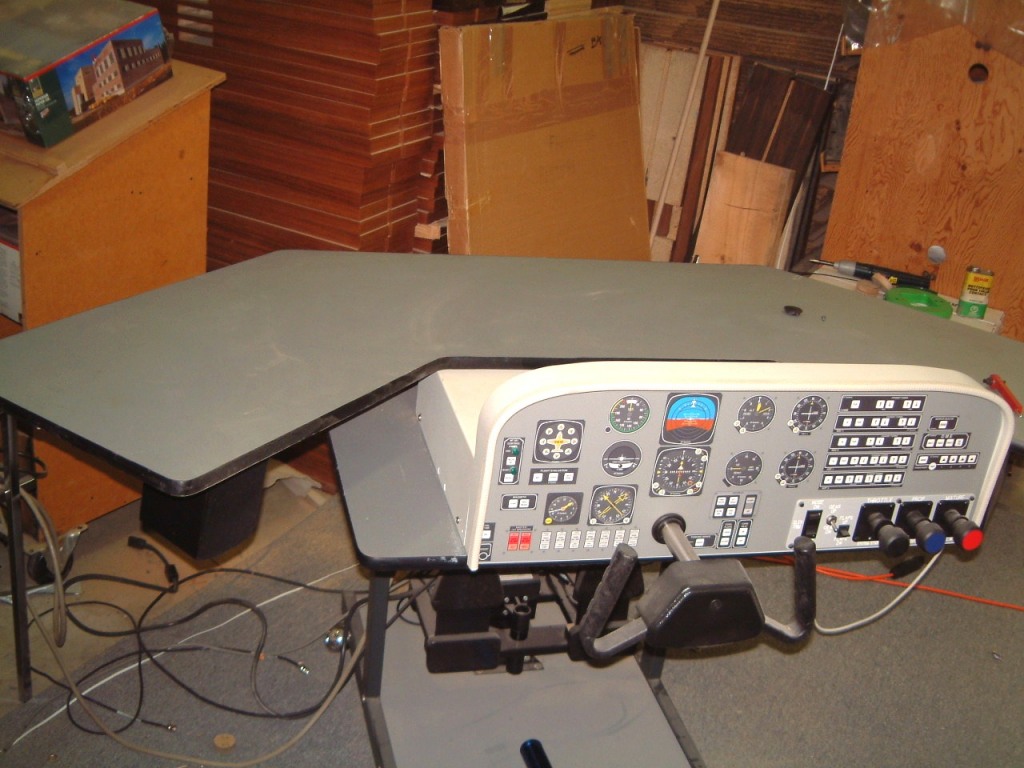
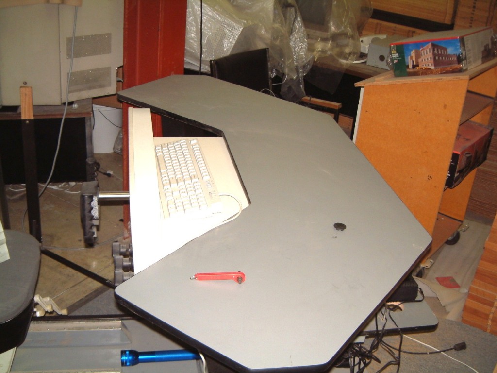
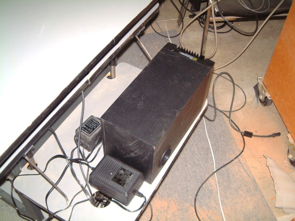
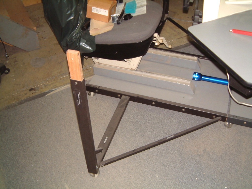
I bought the pilots seat from a parted-out Cessna 177 and had to build a fiberglass mold for the other side of the seat trimming panel. I was able to obtain some seat rails as the seat can be adjusted in the usual way. Frank at NT Systems brought out a pedal system with brakes. Prior to that, I, in 1987, had an older NT system without foot pedals. I built my own version using hanging pedals. The problem was, that these were too close together and we had to set up the simulator on a rented table. The #?$*@ pedals used to slide on the carpet whenever a would-be pilot would over control. We were used to 2000 + hour pilots running off the runway's end whenever, under near panic braking, the would slide on the carpeting. We were accustomed to the weird comments that experienced would utter at the end of some flights.
I have been asked (on too many occasions), for some more details, of how the Flight Simulator was set up for sound. I used two of the Cambridge Soundworks speakers for the ambiance speakers. I drilled a hole in the plastic case (using a sticky material on the drill to retain the cuttings), and tapped a 1/4 x 20 hole in the cases. I used a countersink through the Formica to countersink these holes. Then I bedded the tops of the speakers in a silicone semi-adhesive material, normally used in museum displays of glass as it doesn't leave a mark.
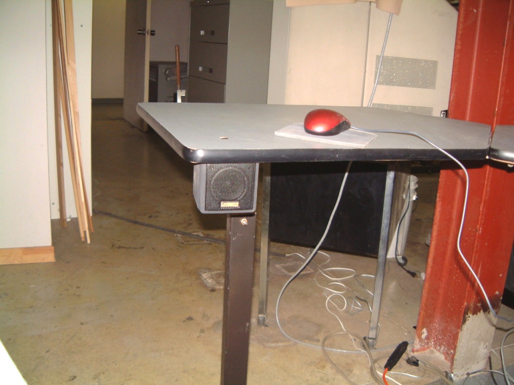
The overall appearance of the unit is different since I added the 22 inch Dell monitor. I was considering adding two flat screen monitors on either side of the Dell as I was quite impressed with the image I had when I was running FS 2002 on the BARCO 808s. However, when I first learned about WidevieW, I decided that it might be time to reconsider. You must appreciate that there is no possible way to fit the whole flight simulator console into the media room!
Therefore, I will have to live with the revised unit. (for the time being).
The left shot shows the rudder pedals (and brakes). The right one is the whole thing, you can see where I allowed for two more monitors on the sides. I wanted to resurrect the idea of a computer where the motherboard is immersed in Stabilant. But, I haven't sorted out how I can add cooling fans. My first idea was to pre-heat the Stabilant to 110 degrees F, at which point the Stabilant is fluid enough to carry the heat away from the CPU. But I don't know how it will behave with a graphics board that requires a fan to cool the chip? I will have to postpone this idea for the time being!
The 22 inch Dell monitor had a severe red-gun misalignment that proved impossible to fix. I spent too many hours in an attempt to use the 'gun bias magnet' to correct it. I dislike getting too near a HV supply anyway.
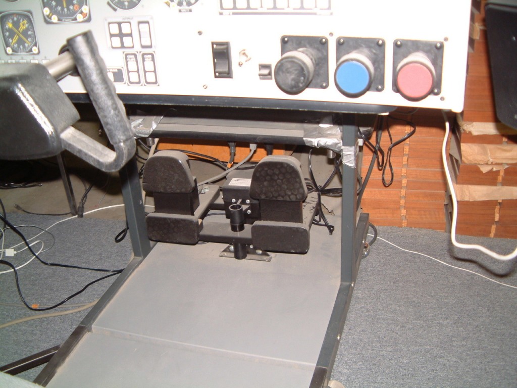
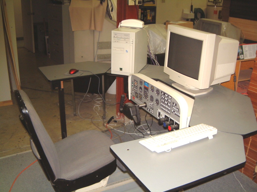
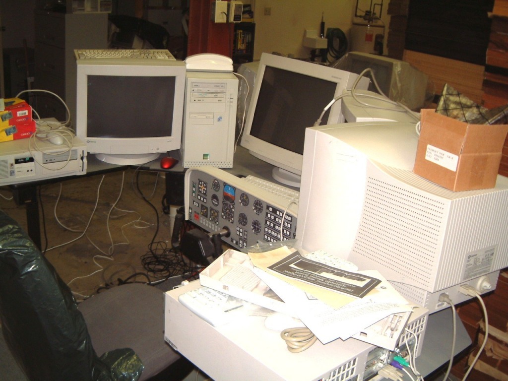
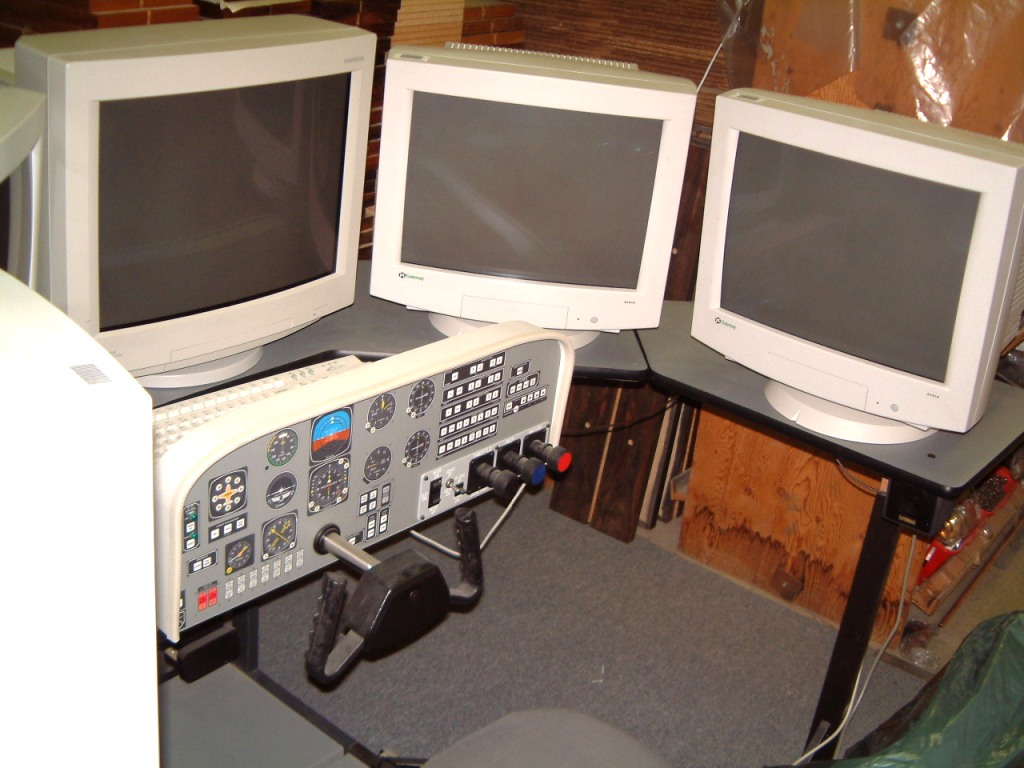
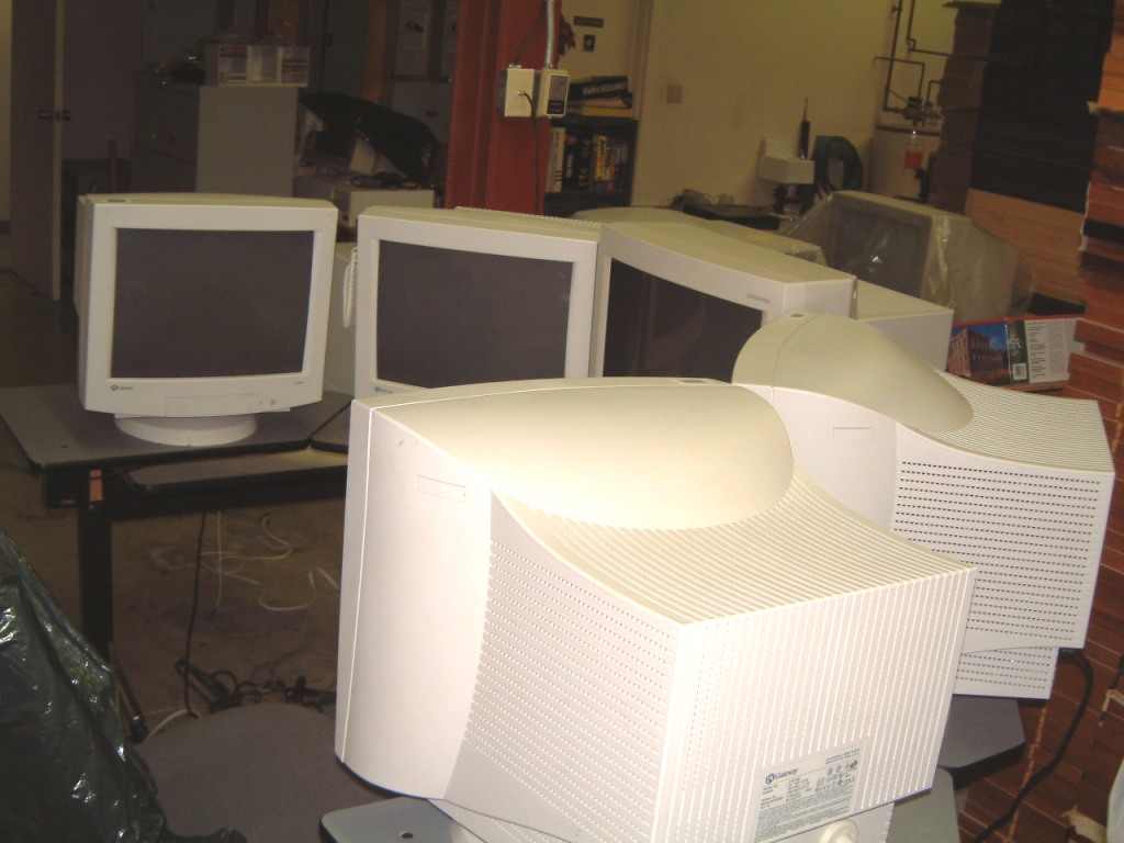
I was able to purchase four Pentium Two computers that were set up for LAN servers. It wasn't any problem to connect them up as clients. I had to add PCI modems and do all these new installation of Windows 98 (second edition). I was able to buy four copies of Microsoft's FS 2002 and register all the software Thereafter, the modems were redundant.
As the NT Systems simulator console I was using was compatible, I then installed a program called WidevieW. In case anybody was wondering, NT Systems stands for Novel Twist, rather than Microsoft's Windows NT.
I was able to get four Gateway 19" monitors as well as a 21 inch Mitsubishi Diamond monitor for the center of the 'cockpit' which requires a higher-angle of view. The 'Main' computer is a older Pentium !!! that has a LAN connector for the output that connects to a D-Link four port router (DI-604). One minor problem is that the 'four slaved' clients won't show 'dynamic' scenery as they have to run in 'slew' mode. The right-most clip shows the mess on the desk with one of the monitors still in the shop at the back of the plant. I finally moved the old 37" monitor to the rear of our carpentry shop where it will reside until I locate a customer with a 3/4 ton truck and four 'warm bodies' to move the monster.
I finally set up the four 'client' computers on the castored table with the main (LAN server computer at the edge). As the wires couldn't be cut to length, there had to be excess wiring. The AC power for the five computers was easy to connect with a short five receptacle (four for the computers and the fifth for the LAN supply). This was connected to the UPS, as was the main computer and the central monitor. The other four monitors were connected to the non-UPS receptacle as was the printer and the fight simulator console and the speaker amplifier.
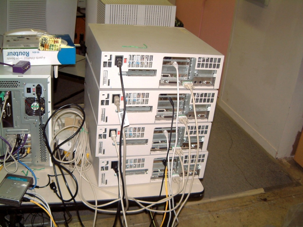

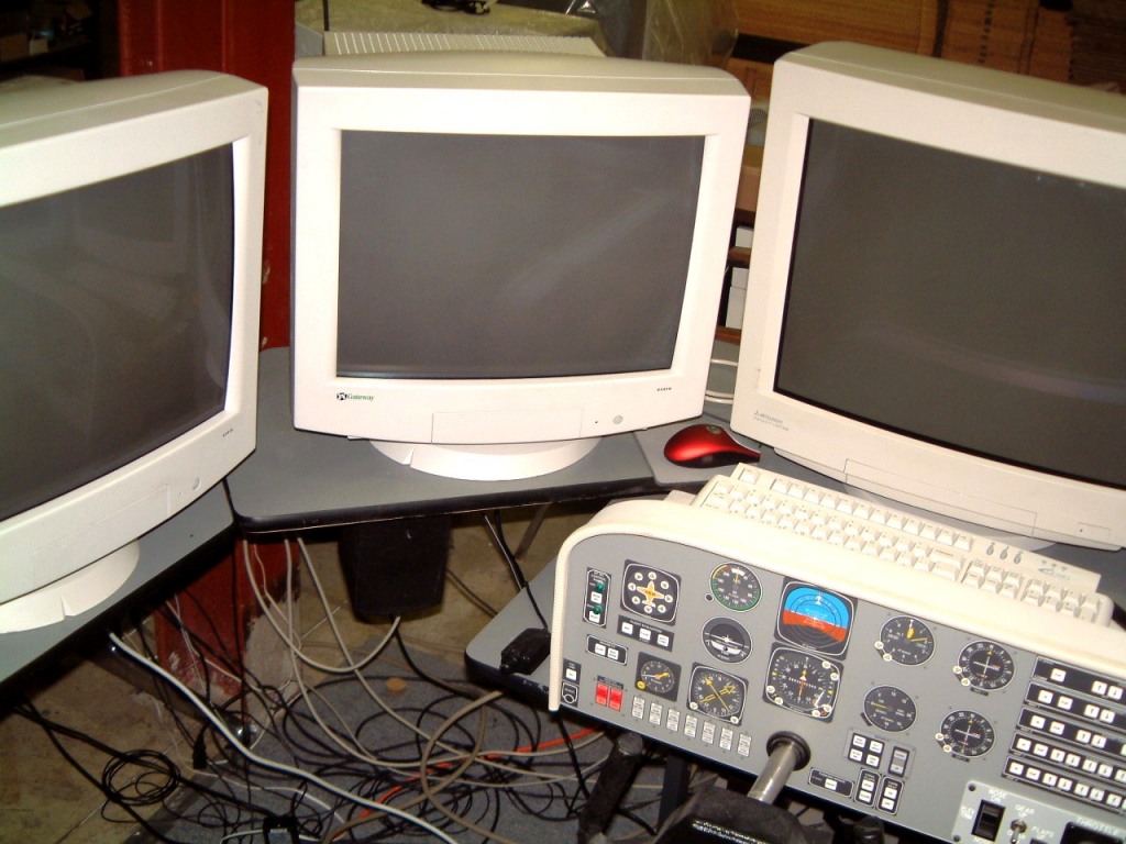 .
.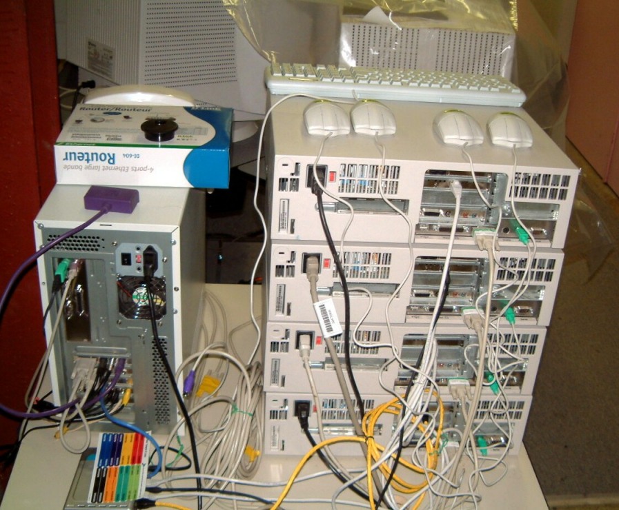
Setting all
thoughts of galloping megalomania aside, this is a series of shots taken during
the set-up. One of them shows the single seat 'cockpit' with five large
monitors surrounding the 'pilot'. The center (21" one), as I said, is set
with the 'top' of the screen a bit higher to allow more space to look upward
(well, no a hell of lot), more. At the right and left (at a 45 degree angle) will
be two more 19" monitors for angled lateral views. Then, on each side will
be two more 19" monitors for the view to the sides. Perhaps I can remove
the stands from these two side-viewing monitors, to enhance the illusion of a
high wing airplane (such as a Cessna 182 RG).
After some %$#@*!!? words when I found that one of the mouse extensions was faulty (after I put ties around the four extensions), I got all five computers working together. The keyboard switcher idea was OK, but I had to press 'Alt' so many times to view the menu (this freezes the motion + the sound) that I rearranged the keyboard. I resorted to the use of a KVM switchbox. (I don't have to switch the monitors). It makes it MUCH easier to use! I forgot that the switcher requires the use of all-male connectors (so I saved myself the task of removing eight sets of cable-ties). By using ten-foot extensions and drilling a set of holes for plastic bushings, the flight simulator console is actually neater than I expected! The only addition will be a cable tray at the rear of the console. This will be divided into AC supply and monitor cables on separate levels. Then, time permitting, I have to organize the audio and speaker cables so that (and I shudder at the thought) we can, once more, take the 'thing' to shows!
I was able to take some photo's of the flight current simulator and here they are.
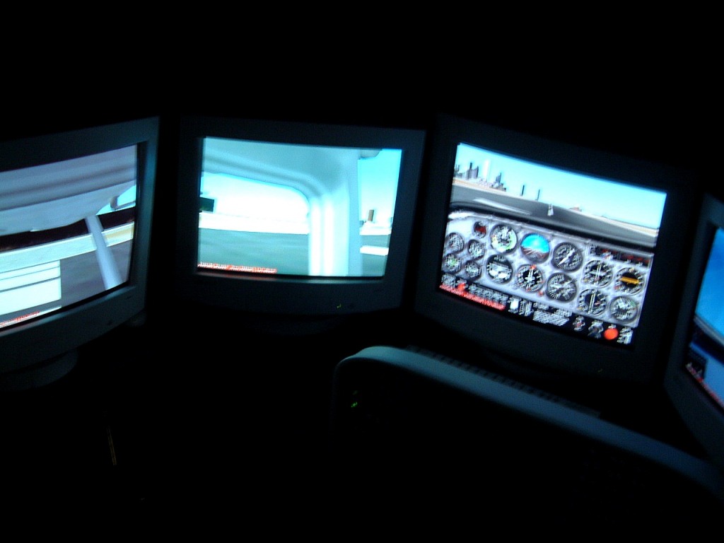
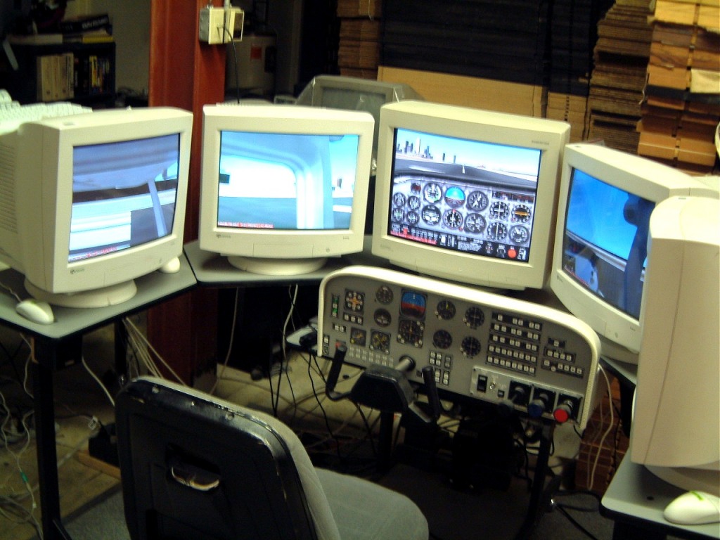
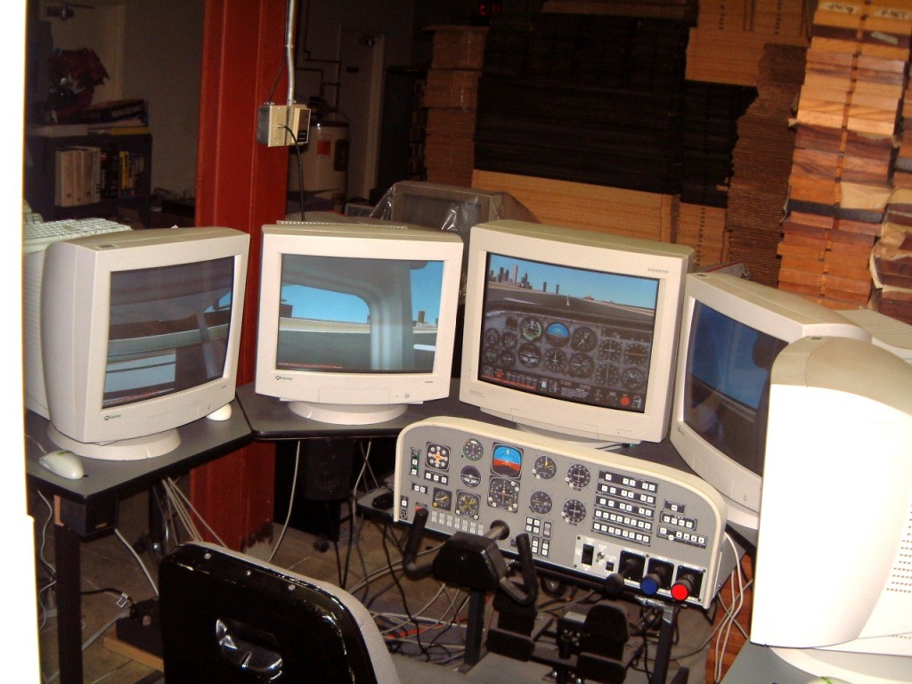
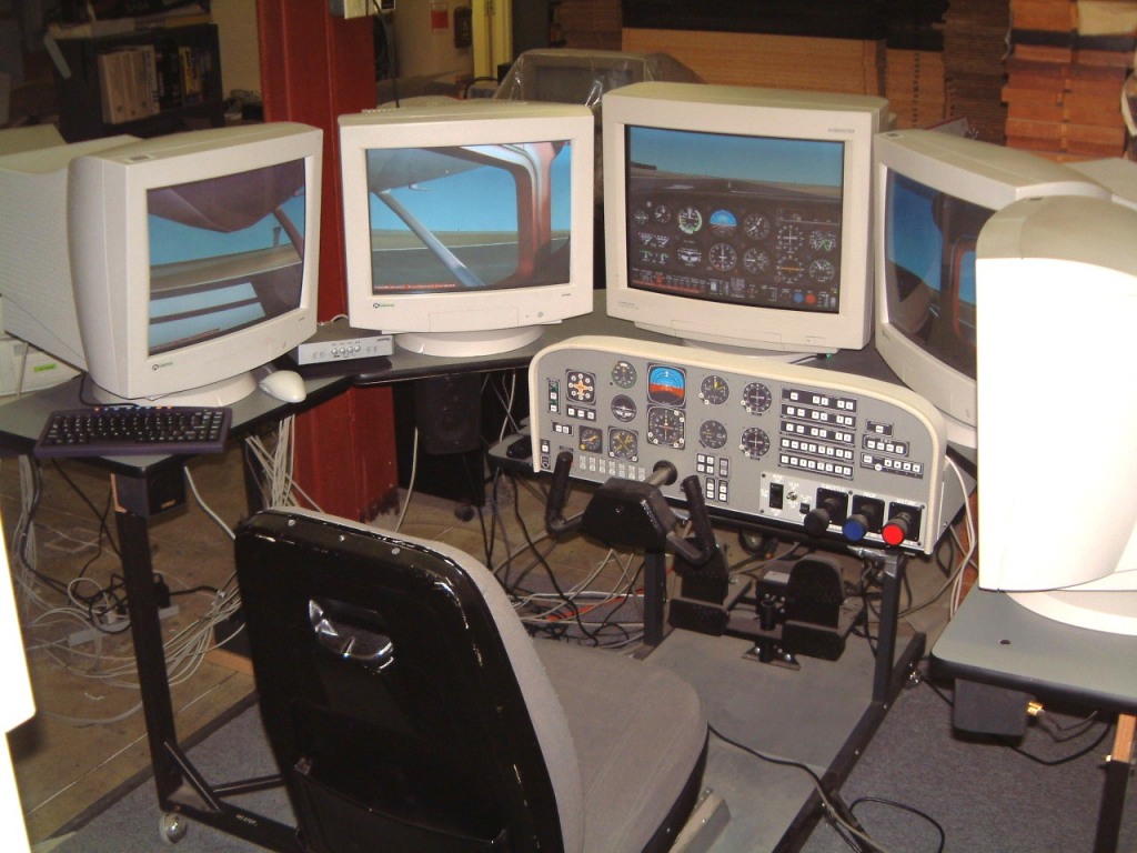
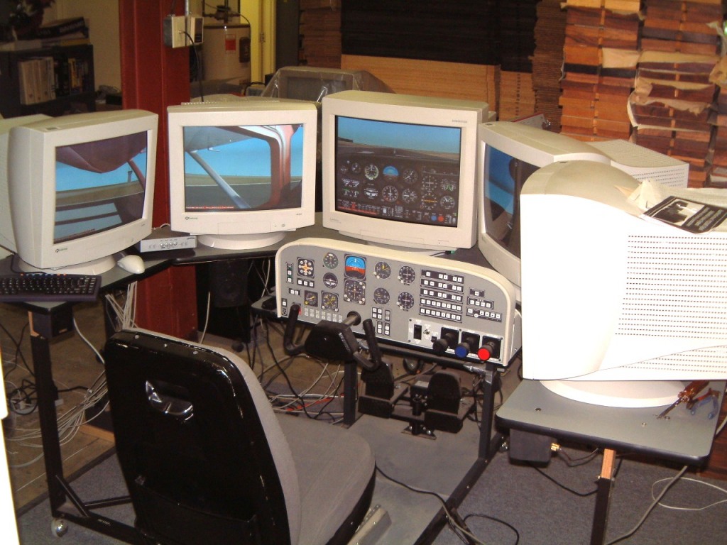
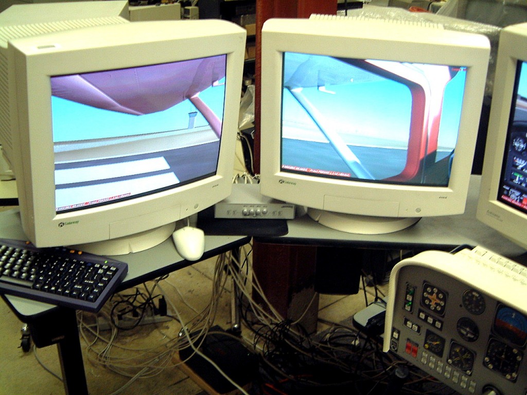
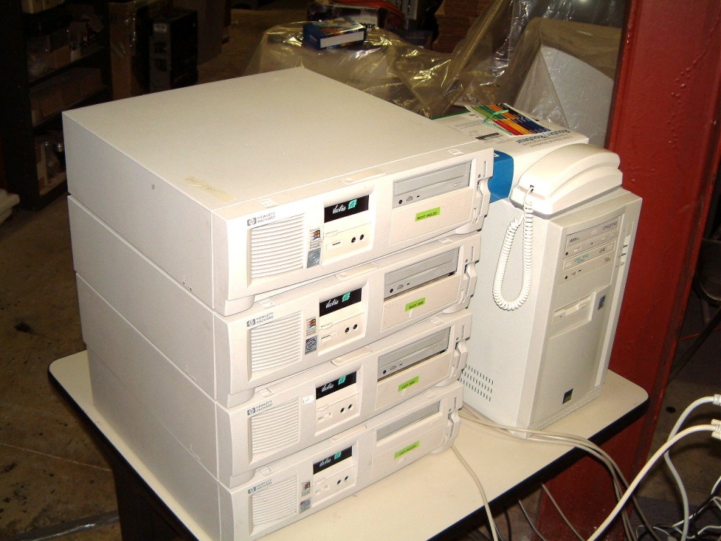
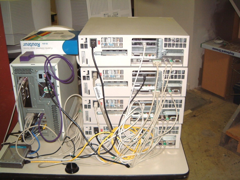
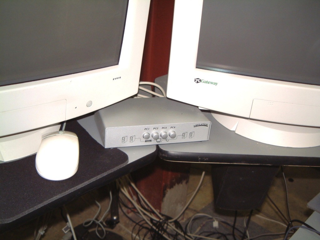
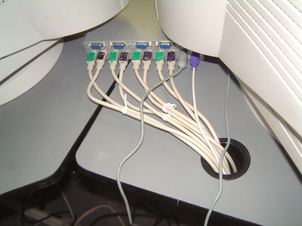
I have to add some comments to the use of the WidevieW program. It uses the Novell IPX/SPX protocol rather than Windows usual TCP/IP. Although, Win 98 can handle three different protocols, IPX/SPX is easier to configure. The only other protocol is NETBUI which is the fastest, but it does not support routing. It took some time to change over as the four HP Pentium 2 computers on the LAN, as 'clients', had been using TC/IP. Fortunately, the D-Link router could be used as a 'hub' and its usual set-up software was not needed. It has its own firewall and so long as the internal chipset's are the 'current' ones, there was not any problem. But, if all the computers are using Win 95, the change to IPX/SPX can be done, but the steps involve setting up the Ethernet Networking cards to communicate by MAC-Addressing using the card's internal network address (if it has one). See home WindowsNetworking.com/.
Look under IPX/SPX basics.
The arrangement shown that placed the keyboards on either side of the 'u-shaped' setup had to be changed. Now the 'server' keyboard is centered under the twenty-inch monitor. I had to make a tilted support so that I could reach this keyboard without attempting to wiggle-out from under the 'yoke' to stand up. If I install a normal seatbelt arrangement (one anchor to the left, one anchor to the right, (perhaps one anchor at the center), then the two over-the-shoulder straps anchoring to a bolt-on (and reinforced) extension of the two side-rails that rose diagonally to twin columns about ten-inches apart with an anchor at each side.
Here is another set of pictures of the simulator in operation (I had to 'pause' it to take these photos).
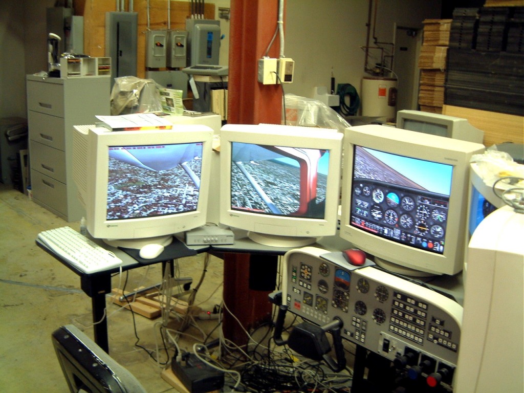
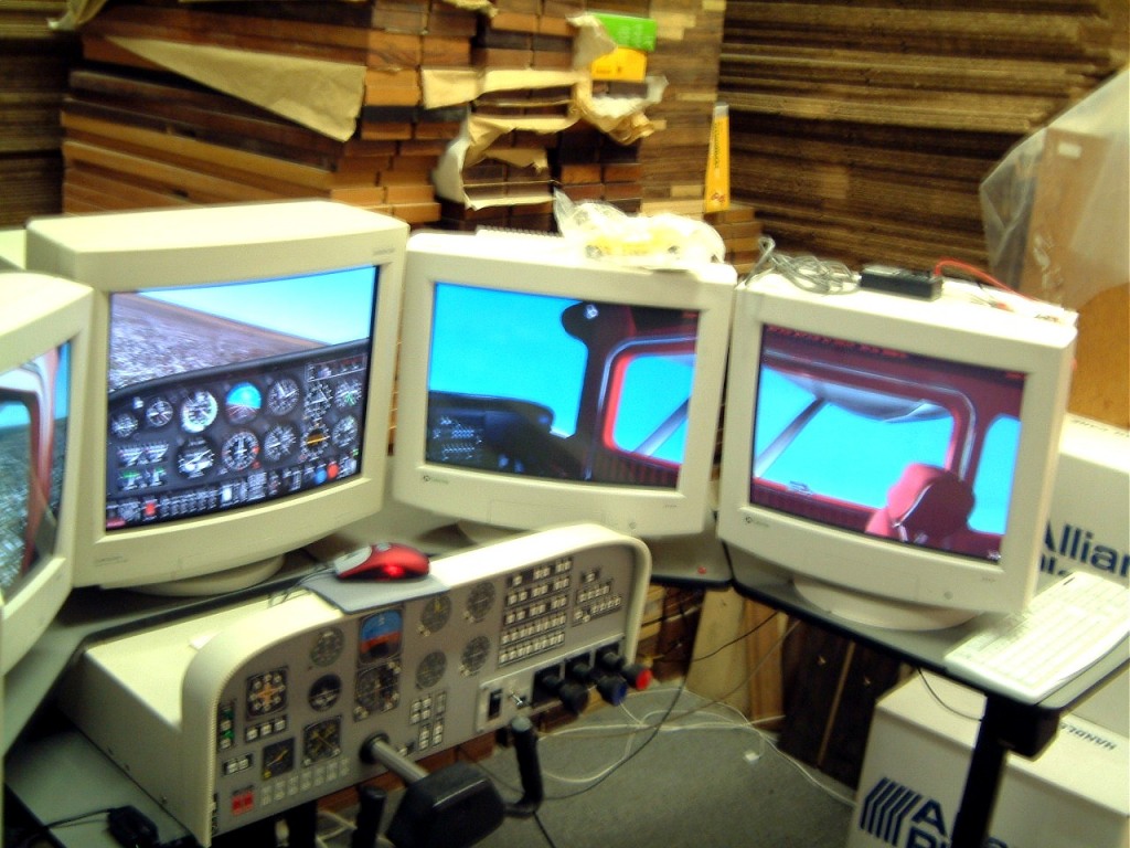
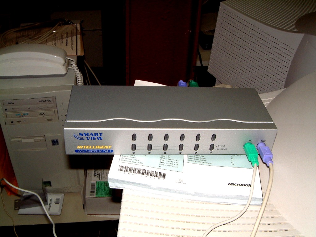
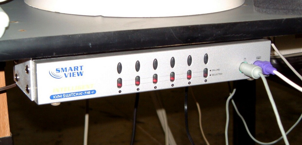

Use of any simulation program requires much more memory than usual. I had to resort to the use of 6 Gb of virtual memory in the 'server' and 4 Gb of virtual memory in the four 'clients'. Remember to release the 'parking brakes' in all four clients then switch to slewing mode in the clients as well.
Do not use the NetBui protocol; it is fast but it cannot function with multiple clients.
Another problem I encountered was some of the mouse and keyboard connectors pulling out of the male connectors. I had the mouse and keyboard wiring cables tied together with twists. However, both connections seemed to fail at the same time. The remedy was to get a strain relief clamp for each pair of wires. This solved that problem. I had to do the sane thing to the stack of computers. In that case, I made up a long thin clamp to accept a pair of cables at a time, the next pair was the height of a computer higher. The lower part screwed to the table-top; acting as the strain relief for all the mouse/keyboard pairs. If I can locate a pair of Dimco-Gray fasteners I can disconnect each pair and then take them off the Dimco-Gray fitting in one string. That way, I can disassemble the console bits and pieces easily?
But, there was an unexpected problem. After several 'flights', the simulator 'hung' as the right-side monitor stopped tracking. Then, the left angled mouse ceased functioning. What could be happening? I didn't have the time to sort it out that day. I had problems with the fine wires in come connectors breaking under strain. So it was time to go out and get a twelve foot, Four-Pack set of color-coded mouse and keyboard cables. I had to bite the bullet as they only came with a monitor cable attached. But they were rugged. While I was at it, I speculated whether it was time to use an 'intelligent switch'! I could use the 'dip switch' to disable the automatic switching so that I could manually control the selection. The major advantage was that it used a power supply for the electronic switching! From experience I knew that it was less lightly to introduce artifacts.
First connected a keyboard and mouse to the balky computer. I behaved. So I used one of the new set of cables on the new switch. It functioned without a hitch. So I added another computer to verify that the switch could work. Well, I will have to fabricate a bracket so that I can mount the new switch under the counter. As you can see, there is no room between the two monitors! I forgot to give out the switch manufacturers name, so look for the Smartview Intelligent KVM switch (model IC-716-1) powered switch. This is more much more expensive than the previous (non-powered) 4-port KVM push button switch, however it is worth the price. Now, I have been asked if I plan to expand this Flight Simulator. Yes. There are so many off lease Pentium 2's that were once used as 'clients' in customer's order desks that they are ideal for use in multiple screen simulators. The computer cost is about $100, less than a good used nineteen inch monitor. Remember that you will need a router to act as a 'hub' as well as a KVM switch plus a faster computer to act as a 'server'. Make sure that the server has as much memory as the mother board can handle. Then, you can add 'virtual memory' to make the screen updates as fast as possible. Act as you were building a machine as a 'gamer'. So long as the display board is fast, such as an ATI with as much on-board DDR memory as is offered, (64 to 128 Meg) - (make sure that the mother board has an AGP slot)! I was building a very fast Pentium four to act as the server for the flight simulator using windows 2000 until I found out that only a 'beta' version of WidevieW is available. I planned to use the Matrox Parhelia to operate three screens, and ----- I have more than enough to handle for the time being.
Oh, the new six port switch mounted neatly under the left 'wing', leaving much more room on the top. Oh, a couple of people who are interested in WidevieW setup, e-mailed me about why I didn't use all three connectors (monitor, mouse and keyboard) with the KVM switch. There area total of five monitors for the Flight Simulator, all of them are in use, therefore, the monitor part is never used. I admit that I could have used the monitor connectors (one for each computer and monitor), but the five monitors surround the 'pilot' and it is easier to use shielded cable for each monitor. I tried ferrite clamp-ons on two of the monitors (both at the computer and monitor ends) and couldn't see any difference. That might change. For now I have used clamp-on ferrite's on the keyboard and mouse cables for the KVM switch (at the computer ends only). I have used them on the server's mouse, keyboard and both ends of the Comm' cable as well as the rudder connection's. I used the 5/16th diameter monitor cables only for strain-relief at the switch ends. I clamped the monitor cable with a Heyco Nylon Cable Clamp - part # ['j305] by using 6 x1 inch drywall screws with a very small cup washer. I used the same arrangement about six inches away. The mouse and keyboard cables have three inches free in a 'U' shaped slack.
The shielded monitor cable I am using is CVGAM-15 (HD15M to HD15M) 15 Ft.VGA/SVGA CABLE, Triple shielded -- FOIL, BRAID ? CONDUCTIVE COATING; 3 Wire Co-Ax + Four Twisted pair.
The color coding I am using is:
Brown- Monitor 1 Right Side - 'client' -
KVM # 1
Red - Monitor 2 Right Angled - 'client'
-KVM # 2
White - Center Monitor - Server - not switched
Orange - Monitor 4 Left Side - 'client' -
KVM # 3
Yellow - Monitor 4 Left Angled - 'client' -
KVM # 4
Green - Monitor 5 Right rear Angled
-'client' - KVM # 5
Blue - Monitor 6 Left rear Angled
-'client' - KVM # 6
I have located a source for Compaq Pentium 2 'clients' and bought several of them. Time permitting, I'll use two of them for the rear (angled) left and the rear (angled) right. The table wings will accept the weight of an extra monitor on each side. However, I will have to fabricate a steel framed support for the KVM switchable keyboard. I only need the keyboard to enter the passwords for the 'clients', release the brakes and to enable 'slewing mode'.
(Still not used yet, or even considered for now, Purple - Monitor 7 for View for looking Back and Gray -Overall view of aircraft Monitor 8).
Here is a full size copy if the labels I have used on the flight simulator. In
my case, I printed them on a sheet of gloss photo quality paper and after
trimming them to size, I used an adhesive that would not harm the paper.
|
CENTER – SERVER |
|
RIGHT ANGLED MONITOR |
|
RIGHT SIDE MONITOR |
|
LEFT ANGLED MONITOR |
|
LEFT SIDE MONITOR |
|
LEFT REAR ANGLED MONITOR |
|
RIGHT REAR ANGLED MONITOR |
|
LOOKING TAILWARDS |
|
SPOT AIRCRAFT |
The Mice and Keyboard connectors use the same color coding - on the vinyl tape.
Another corespondent using WidevieW on three computers, has been bothered by 'computer hang-up'. There seems a sequence that works for me. First, I start the server' computer. I open Microsoft's Flight Simulator 2002 at the selected airport. I press 'alt' so that the menu is at the top of the FS screen. This stops the program. Then I select 'modules' and WidevieW. I click on 'start' to get it running. Then I press 'alt' again so that the engine sound returns. Now, WidevieW is running. Then, one at a time, I start FS 2002 on the other computers. I press 'period' to release the brakes. Then I press 'Y' until 'SLEW' comes up with a Red frame on the lower right hand corner. The coordinates and the air speed is visible at the top left hand side as is the SOUND' mode for that 'client' computer. When the brakes are released on the 'server' computer, all the computers 'track' the server. It is essential that the computers receive their AC power from a battery-backe'd up UPS. Make sure that the computers have good AC power cables as a momentary interruption of power can stop that computer's tracking. When the airspeed doesn't change and all motion ceases, the only thing to do is to restart the 'client' computer, at times, it will resume tracking. If it doesn't work, you may have to reboot all of the computers.
With WidevieW 2004, there is a ' Toggle switch' (in the upper left corner) on each monitor (it can be hidden if needed). With all of the the switches 'ON', the screens track perfectly. WidevieW 2004 will work with MS Flight Simulator 2002, however there are extra aircraft on FS 2004 that have to be deleted if you are using FS 2002.
I was surprised at how much easier it was, to get this system up and running; once all the glitches had been rectified. Now, even without the 'fried' E-prom still in place, I spent several hours 'flying' over the Toronto area. When the e-prom was first installed, a communication cable had to be connected from the 'server' to the 'modem' port on the NT 360 console. This made the use of the simulator better. Without it, the aircraft will fly, but it is more prone to control problems.
The simulation screen upgrades are fast that it is a delight to look out a side window as you 'fly' over a familiar area. The next day, I reset the system to the San Francisco area, and did a landing at the airport. After that, I took off from Las Vegas, and flew down to the dam. I flew eastward, following the Colorado river upstream over the Grand Canyon. Then I headed south over Flagstaff and down to Phoenix. I headed east past Tempe and veered northeastward and then over the northern rim of the Superstition Mountains. The following day, I started out from Phoenix once Again. I must explain that I had flown in this area several times in my Cessna 182, so that I wanted to see whether the Flight Simulation program replicated the actual flights in this area. I then headed northeastward to ShoLo and to the Zuni area. I wanted to follow a previous flight (that I'd made several times in my Cessna 182) to eventually land at the Gallup airport. As the simulator flight was in 'real time' alas, I had to shut down the system all too soon.
I have three more Compaq Pentium 2's that I can use. These are all running Windows 2000. I think that I may set one up so that other people can watch the aircraft. (I will use a separate keyboard and mouse so the KVM switch is not needed). There is a possibility of setting this view to much further away, so much more of the 'background scenery' is visible. Hmmmm...I'll have to think more about it!
I have to find a way to install a fibre-optic light-pipe from a central source to provide the equivalent of eyebrow lights on the instruments. At least so that I can see where I have to press on the membrane switch. Perhaps I can purchase a real eyebrow light, machine it to get a pattern. I can cast it in RTV silicone and make clear castings. I can then imbed the fibre-optic stuff to proved the needed illumination. Real-soon-now!
RSSN has arrived. The table holding the five computers has suffered a fractured caster, and I am afraid that it might be a terminal case. Rather than dismantle the old table in the hopes that I might braze on a new bearing, I went to the local IKEA and bought a 'TIMRA'. This has a hexagonal core with a top surface of Oak Melamine and an underside of waterproofed masonite-like material. I have altered these before; so long as the cutouts are reinforced on both sides with something like plastic bushings, they are durable. What I mean by reinforcing both sides is that, I use an appropriate computer wiring bushing on both sides. I generally use an off-white bushing on the upper surface and a black bushing underneath.
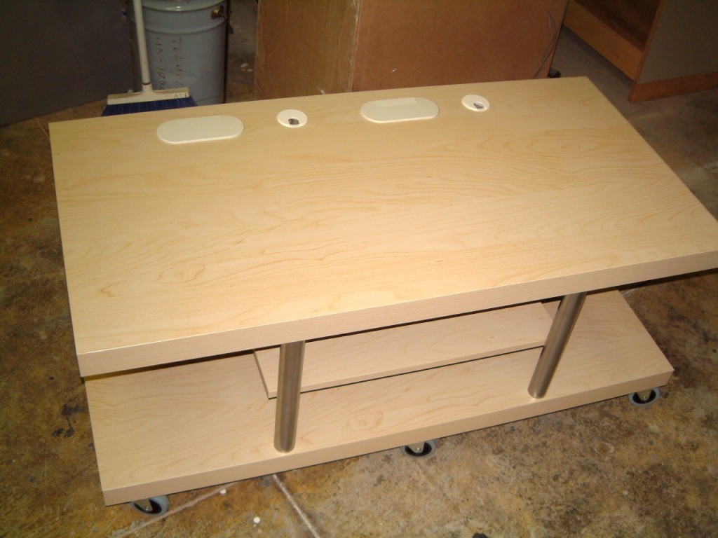
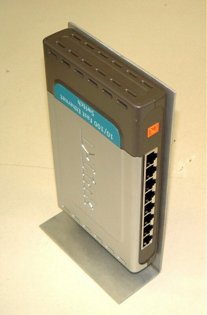


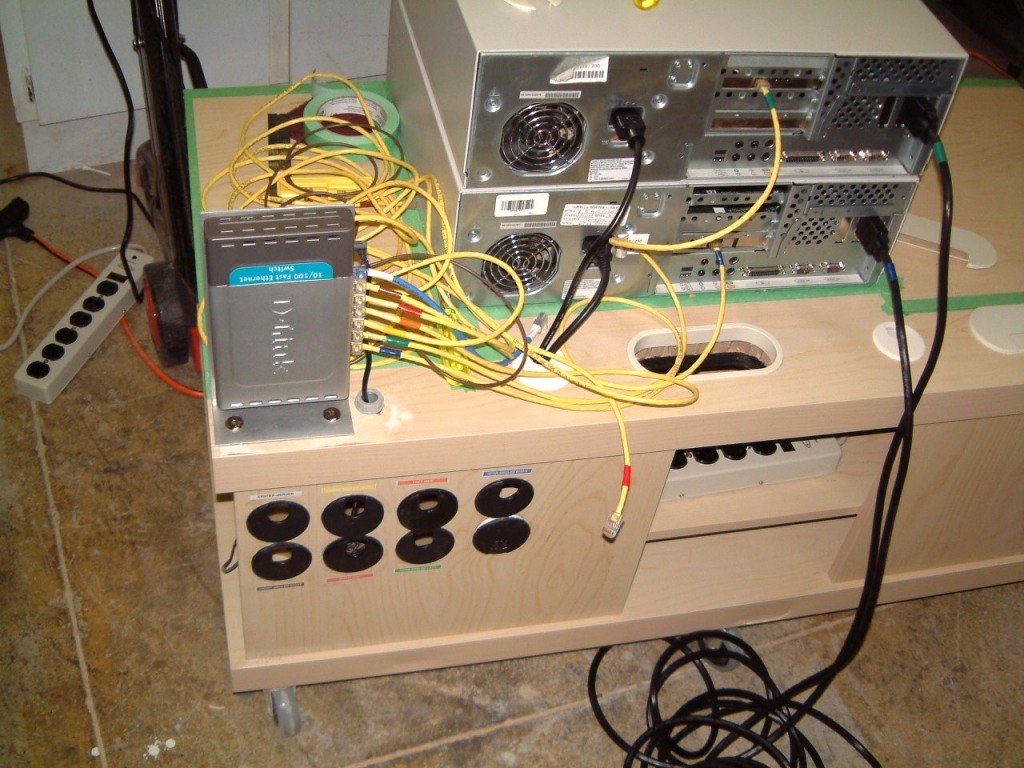
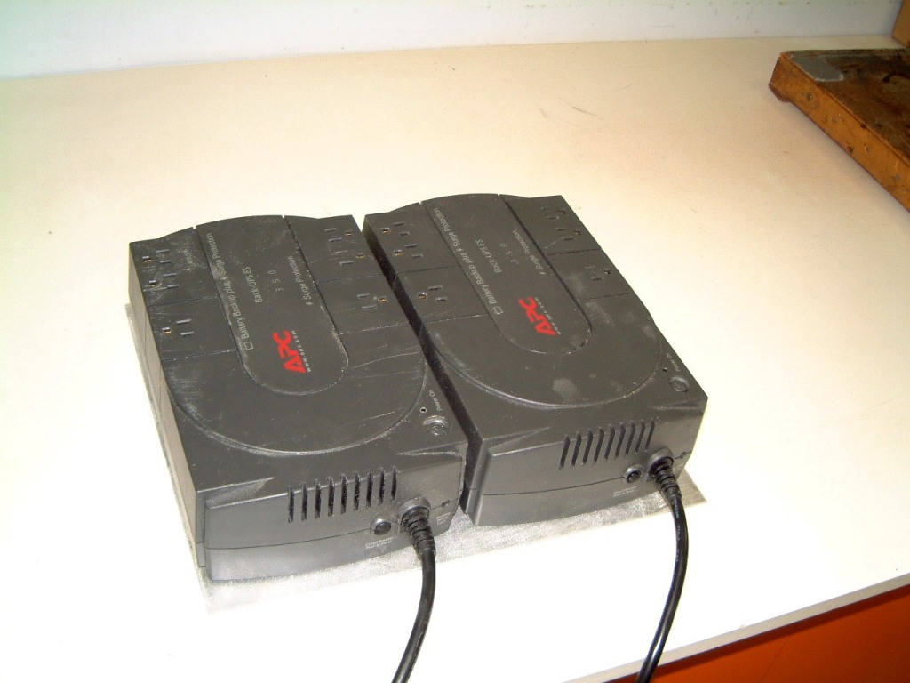
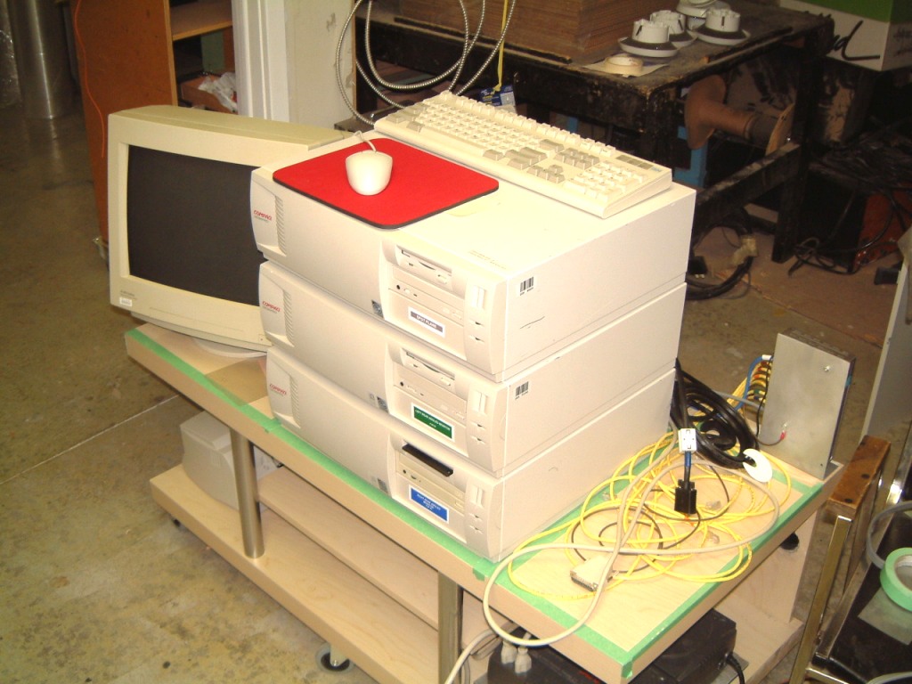
This will give you an idea of what it looks like. At the rear is a long bushing for cables followed by a smaller one for AC power, then, another long bushing for cables and another for AC power. There will be a battery back-up UPS on the shelf with a pair of Belkin Surge-master enameled steel AC receptacles, with the 'normal' type of receptacles rather than the molded plastic type. To the right (not to scale) is a vertically D-Link eight output router used as a hub. The next clip shows the router mounted in the new IKEA computer table. The green tape is what I use as an aid for the location of the computers etc. The next shot shows the two Compaq Pentium 2's in place as I attempt to neatly route the wiring (including AC power) in a logical and neat fashion. I decided to use a separate UPS for the computers, the central monitor and hub, with the older UPS supplying the six peripheral monitors, the KDM switch power supply, the sound and the NT Systems Flight Simulator. An obvious problem was the routing of all the wiring. I added a common ground wire starting at the router, then on to the server, followed by the six clients. By arranging the 'ring' of monitors around the pilot it is not obvious that there is a wide gap between the angled right rear and the angled left rear monitors.
The top computer of the stack, is for the 'Spotter Plane'. It has its own keyboard and mouse.
More on the revamped Compaq Pentium 2 computers that I an using for the rear angled view (both left and right). I added more memory 'sticks' to both computers and now when used in 'slewing mode' the updating is a fast as I could wish. Remember that these views are to aid the peripheral vision in order to get an location 'fix' when in a crowded circuit flight circuit.
I remember just how often I had to look back over my shoulder when someone who was unfamiliar with the airport 'broke into' the pattern. This habit is hard to break. I remember when an AD was issued on the Cessna 182's muffler. I had the a FBO's licensed aircraft mechanic remove the muffler and install a set of 'doublers' in the exhaust connection as required by the AD. I verified that toe job had been properly signed off before I flew the aircraft. I even did a three hour flight to verify that ass the DUZ fastners were tight and that al inspection covers were in place. I had to fly down to Phoenix for a Dealer Show. Luckily I had been reading an article in "Flying Magazine" when I stopped overnight at a motel near Witcha expecting to leave as soon as possible next morning. So when it happened to me about seven hours later, I was able to react. As soon as the exhaust noise tripled, I looked around and saw I was in gliding distance to the Valprasio airport in Indiana, I switched to the emergency frequency while I shut down the engine, trimmed the 182 and did an perfect approach the active runway. As it happened, an FAA inspector was at the airport and he was able to get a couple of students who were doing 'touch and go's' to break off to give me a clear path to the runway. I had enough momentum left to clear the active and coast to a stop near a hanger.
I was surprised when the inspector showed up immediately. He checked the maintenance log and swore when he saw that the reinforcement had been signed off without having been done. As the job had been done in Canada he could only file a report that would be sent Transport Canada.
However he was still at the airport when I was able to use a ball-peen hammer and a thick pile of newspapers on a piece from a Moony landing-gear door to make a replacement patch for the burned out hole in the engine cowling. The FBO was able to rivet it in place where the FAA inspector signed it off. The FBO located a new muffler and I was on my way a day later. (You see, I and another friend used to buy sports cars, fix them up. We were able to get an English Wheel and after many false attempts, we became adept at the use of this 'powered pinch roller' to make a fender, if it was needed). So I had a working knowledge of all sorts of useful stuff.
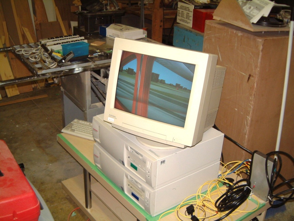
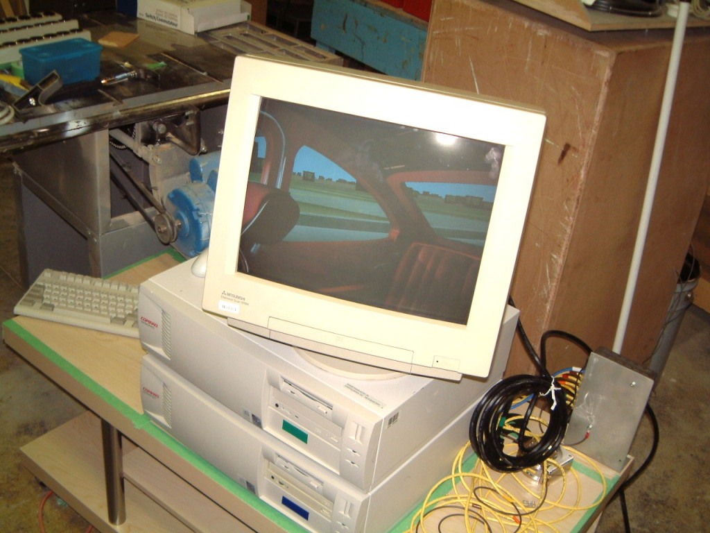 Here are a couple of shots of the rear
angled (left and right) views!
Here are a couple of shots of the rear
angled (left and right) views!
The use of Flight Simulator for night flying is enhanced by the use of the WidevieW program. Here is a typical shot of a night flight on the ground at Buttonville Airport (there was only room for the inclusion of four of the monitors. The lighting is from several low wattage bulbs mounted about ten feet apart. As it was, I had to place the camera in an open doorway.
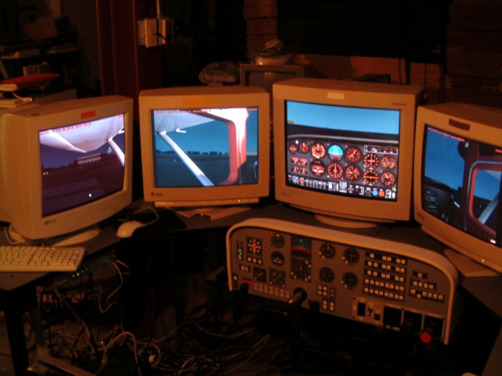
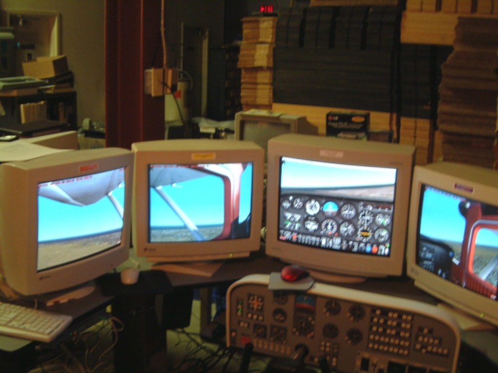
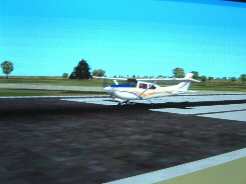
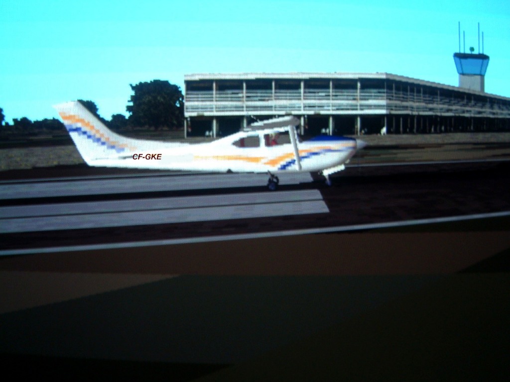
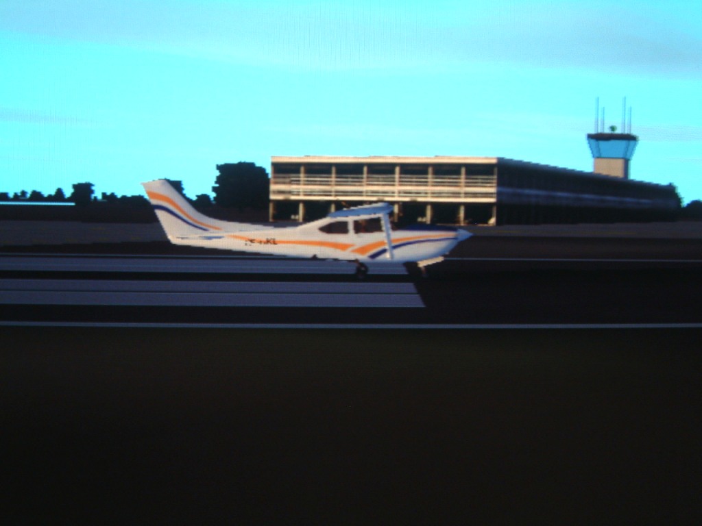 I think that these two
low resolution views in a ''spot plane' format, will serve as a general view.
Therefore, anyone at the side of the multiple CRT setup will be able of see
what is taking place.
I think that these two
low resolution views in a ''spot plane' format, will serve as a general view.
Therefore, anyone at the side of the multiple CRT setup will be able of see
what is taking place.
To change the subject: I have found that the 8-port switch seems to be a much better choice than a hub. Although the hub seems to work, it seems to interact with the speed of the packet transfer. The switch is better! A high-speed Pentium four server using a raid setup of three serial Western Digital 10,000 rpm HDD with a gigabit LAN output should be really great! I can only pray that the clients will cope. I have yet to find out from ATI whether they made a special card for Compaq. It uses a shorter mounting plate for the VGA connector.
Tweaking the frame rate seems to work. Perhaps I really need a 'basic hub'. I tried a 'loaner' for over an hour. It seemed to handle the packet transfer OK. I had used an older intelligent hub from LinkSys when I first tried out the Flight Simulator, but I was using it with the network. in our plant. So we tried an older-cheaper hub on Wednesday May 26th 2004, (today), after we upgraded to Wideview 2004. After some fiddling with the 'rate monitor' from the server and the clients, Wideview performed flawlessly. I spent over an hour flying over the Toronto area. (I had been using an Orbus switch/hub, which prone to overheating when it would 'drop' a computer or two. I grew tired of rebooting the computers when they dropped off line. As I mentioned, I had been stopped cold by seemingly 'minor glitches'. On that basis I was going to use a D-Link 8-port switch. It's still in the (East) back of the plant with only the two Compaq Pentium 2's (plus everything else but the main 'serve' and the four 'clients'). But now I will try out a proper hub manufactured by LinkSys, before I move all the rest of the computers.
Problem! I still seen to encounter a hang-up of the server. It might be a result of Direct-X nine malfunction with the slower Pentium three combined with an ATI all-in-wonder video card.
Well, I tried the switch and it functioned smoothly until the Direct-X nine halted the server. I don't need a firewall as I have one installed on the dial-up connection to the server. It has been set-up to ignore the communication between the 'server' and the 'clients'. So far, I haven't moved the new 'desk ' from the rear (East) computer area up to where I have the main Flight Simulator installation. I will use the D-Link switch. As the whole 'desk' has all sorts of RF traps involved, the new I dislike having to resort to using a milling machine to fabricate a new bracket for the 'hub'.
The shot on the right is from the same computer after we found out why it only reverted to 'safe mode'. After this glitch was fixed, The image is sharper! It is the distant view of the aircraft (CF-GKE - sorry about the color mismatch). I wanted another person to be able to see the aircraft - from a specified distance - as it is being flown. I have three spare Compaq Pentium 2's running Win 2000 (with FS 2002) and I am going to use a spare, set up so that the aircraft can be seen in flight. The hub willing, I will place the monitor (a 17") on top of the two Compaq Pentium 2's (assigned to the left angled rear and the right angled rear). I don't need a KVM switch as the keyboard and mouse are not under the control of the pilot!
I have to admit that I really liked flying the simulator around areas where I had flown the Cessna 182. It is very simple to stop the simulator in order to answer the phone, or take a leak!
September 14th, 2004
A major and extended flight on the new simulator went fine. We have had to redo one computer at work after we caught a horrible worm. We pay our ISP to remove Spam and Virus' at the server end. But, the especially nasty ones still seem to get through. I and our technical expert have spent several days attempting to salvage a Pentium two. We had to export the 'safe' files to another spare Pentium three. One of our largest customers insist on using Microsoft's Outlook Express which Netscape 7 won't handle properly. They are very secure at their end, but as many people know its beset with hackers. I upgrade Ad-aware as soon as they come out. Ad-aware is great for locating 'data miners'. Outlook express seems to attract them!
Within two days of its initial use I had to remove 638 SPAM's and eighteen variations on The Mydoom virus which lends itself to .chaining' in the supposition that at least one nasty will penetrate our server.
To see what the
program is about:
First try a typical flight (no motion or sound):
Then try:
This is the start of some typical Simulator Flights. More will be added as time permits.
Once again, I
have been asked where I located the fittings that I have used. In this case the
round plastic bushings are (white and black) are Richelieu # BP60090 and the
longer bushings are Richelieu #1657630, both from Home Depot. The' Allen' (hex)
head screws and nuts also came from Home Depot, as I purchase them in large
quantities, I don't have Home Depot's SKEW number.
I have had some
problems in the past, with the use of several computers that are linked
together. The main difficulty, is RF interaction. That is why I employ ferrite
traps on the monitor cables, the keyboard cables, the mouse cables, the printer
connection, and even running a grounding connection between each computer case.
This even applies to the D-Link hub and the power-bars. (All have metal cased
'normal' duplex receptacle outlets rather than the cheaper one molded into
plastic cases). The female connectors are very well spring loaded rather than
relying on the solid metal of the plugs.
I mounted the bank of power-bars on a shelf in the TIMRA unit. As these had to be mounted from behind via several filister-head #10 wood screws, so exact spacing was needed. I considered the use of 10-32 filister head machine screws using normal nuts. However, reaching into a confined area to unplug AC cords can lead to skinned knuckles. The intent was to keep the use glitch-free. The idea of loosing a single computer from the set was, to say the least, daunting. These three power-bars have surge protection and are mounted at the rear of the shelf. An EPSON 640 printer is located at the other end of the base, opposite the UPS's.

I have spent too many hours trouble-shooting recalcitrant (single) computers to be cursed with seven prima-donnas. What is not visible is that each power-bar is locked on the shelf with a angle bracket on one end; this keeps the power-bars from sliding-free (unhooking themselves from the filister heads). The male plugs are connected to the appropriate UPS. once more, the Flight Simulator is extremely dependent on all of the clients tracking the server. Therefore, all minor faults can disrupt the smooth functioning of any flight. Refresh rate is most apparent on the server; as the clients operate in a LAN system using a slewing mode, this lessens the demands on the computing burden. A lesser color requirement (such as 16 bit color depth) works. However, all the computers have to share the load - meaning that an errant computer is obvious!
August 11th, 2003.
I have logged each flight (except for those when the Flight Simulator was being developed). To date, I have 857 hours on the DOS version, half of which is under IFR conditions. About one quarter of all flights were at at night. I wrote software for the DOS version for the Toronto-Hamilton-Waterloo/Kitchener-Oshawa-Buttonville area as well. When the MS Win 95 Flight Simulator was released I was still using the subLOGIC ATP simulator as well as the Microsoft release. At that time, the subLOGIC program had better ATC input.
At that time I was using separate throttle and joystick connected to the subLOGIC program operating on a DOS 5 computer.
Then went to another Pentium two computer in our home and installed Flight Simulator using the Win 95 version using the the Microsoft Force feedback joystick. ( I have Flight Simulator 2004, running a Pentium three under Windows XP using another joy stick. This computer was a old Gateway 'pizza box' server that was formerly running Win 98 and had been upgraded to Win XP pro by the former owner. This computer had serious problem as it had been infected by a worm before it was traded-in. With the 'worm still resident, the speed of operation was very slow. This made me suspicious. It took several hours to quarantine the worm so that it could be removed, piece by piece. I downloaded a Symantec program to remove the vestiges. Then I used Ghost to transfer the files from the WD 6.1 Gig HDD to a WD 80 Gig HDD. the computer has a stereo sound on the MOBO. As all the expansion slots are blocked by the case, I had to use an USB port modem. I removed the old CD-ROM and installed a DVD drive instead. The stereo is OK for FS 2004. At least this gave me a reference point).
As each piece is
added to the rig, I will update this file. But I won't promise to keep
each item in chronological order.
June 11th, 2004.
Problems-problems. I found that DirectX 9 was causing a severe problem with the ATI all-in-wonder Pro. I couldn't find out why it would behave properly for several flights (at high altitude) then feeze-up upon descent. Now it seems obvious. At lower altitudes the refresh rate is much higher. At high altitudes the screen refresh rate is significantly lower (except for the instruments). I remember now that I increased the ground-shadow settings. Could this change be the cause the Direct X 9 problem?
September First, 2004.
Well, though I hate to admit it, the computer that I was using as a 'server' was running Win 98 - First edition! We realized the problem when we retired the old server and started to refurbish it for general use as a spare. We increased the size of the previous HDD from 16 Gig to 80 Gig using Ghost and the latest partition Magic. The ATI 2-4 All in wonder Pro didn't operate properly. Even though the computer 'saw' the P?P stuff, they didn't react as they should have. I finally realized that we could not install Media Player 9! It won't install under Win 98 first edition! That must be why we had the problem with Direct X nine, even though the ATI Direct X test program worked. But, after an hours flight using advanced settings, it would lock up!
February 19th, 2004 - in
retrospect
I remember when WidevieW announced that it had been 'ported' to Windows 2000. At he time I wondered if it could make the Matrox Parhelia the logical video card. Could it allow a a single fast Pentium four computer running Microsoft's FS to operate three screens. It is easier to purchase Windows 2000 than to locate additional copies of Win 98. However, the Parhelia needs a fast Pentium 4. The video card will handle a normal 15 pin SVGA plus two LCD displays. There is a possible problem with LCD displays. As part of the display is 'fixed', it can burn-in a pattern of that part of the cockpit that does not move. I have attempted to find out if he central 'window' could be for the 'straight ahead' view and the two flanking monitors assigned to the 'left angled' view and the 'right angled' view?
June 15th, 2004
I have decided that I will build a new 'server' using three serial ATA drives in a RAID 5 configuration. I already have most of the needed parts. It seems as if I will have to reinstall the Flight Simulator in the new (and faster) Pentium 4 computer; using Windows 2000 as the operating system. To stop annoying errors, I will use a RAID setup with three very fast Western Digital serial drives. A possible problem lies on the choice of a rigid mounting for the WD drives. Rather than resorting to a machined aluminum computer case I browsed around among steel cases. I was looking for a case where the hard drives were rigidly mounted. I found such a case where the vertical steel parts were fabricated out of steel where the edges had been rolled over to a small tubular configuration.
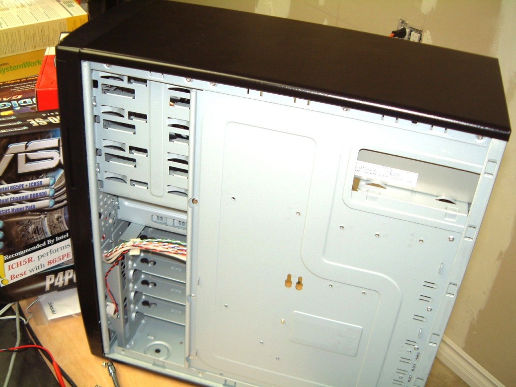
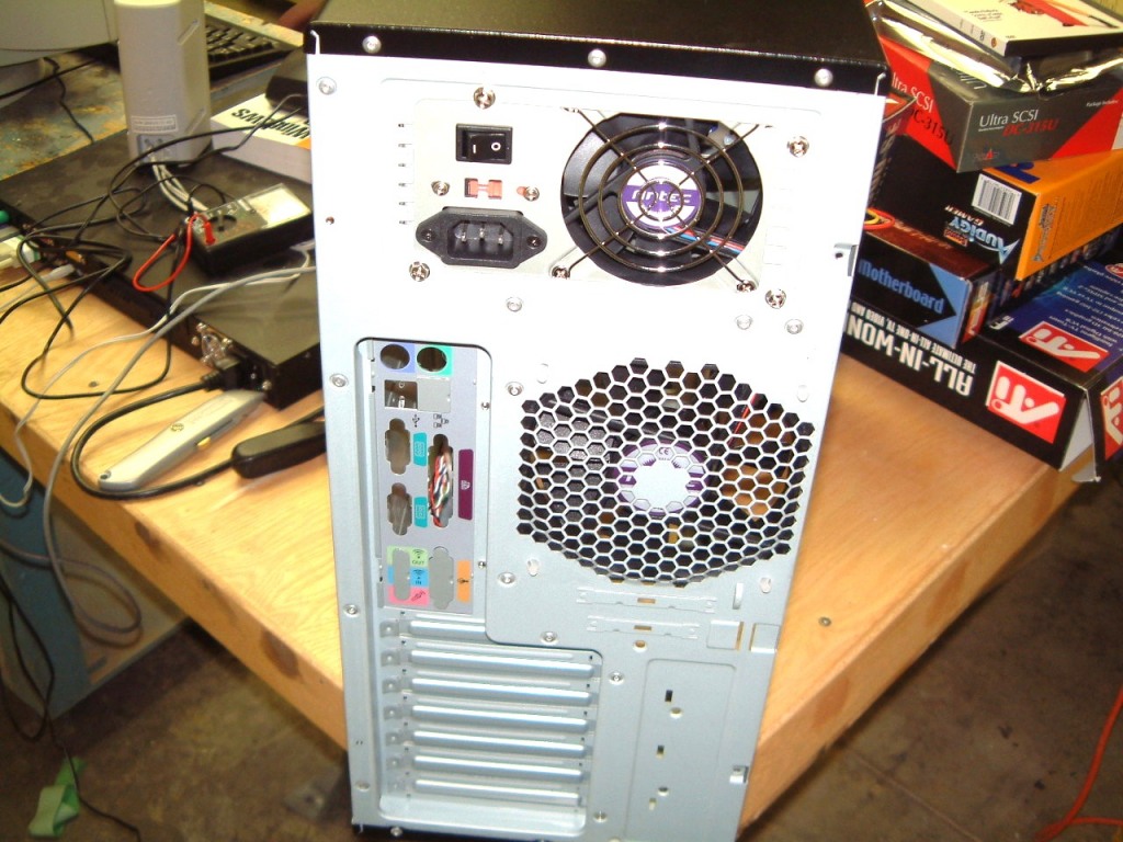
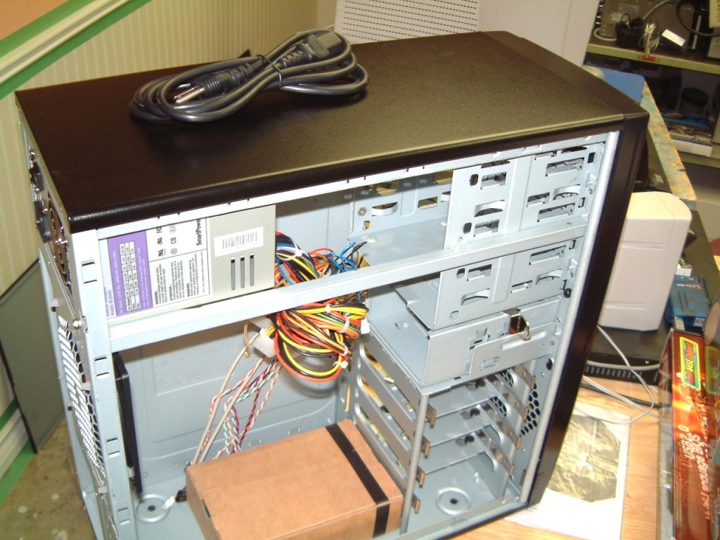
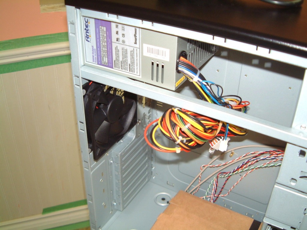 The rear of each
HDD abutted the rolled-over parts of the case. One additional advantage was
that the Hard Disk Drives slid into the case from the open side of the cabinet,
The drives are retained by a sturdy spring clip that makes it easy to remove
any drive. (I can also back-up a drive to a Iomega drive to create an archive).
The rear of each
HDD abutted the rolled-over parts of the case. One additional advantage was
that the Hard Disk Drives slid into the case from the open side of the cabinet,
The drives are retained by a sturdy spring clip that makes it easy to remove
any drive. (I can also back-up a drive to a Iomega drive to create an archive).
I selected the AntecSKL3700-BQE case but decided to replace the Antec power supply with a 600w Enemax power supply, because of its two fans. The case itself has a 120 mm exhaust fan on the rear of the case with a mounting for another optional exhaust fan on the front.
I plan to use an Intel motherboard #D875PBZ Pentium four with Megabit LAN support. The next clip is Western Digital 74 Gig 10,000 rpm 8 Mb cache Serial ATA hard drive. I plan on using a 3ware serial RAID controller
 The right shot obviously shows the HDD sans- top panel.
I have an Audigy 2 platinum 6.1sound board I was saving for use on the media room computer. That is until the 7.1 version came out. As I can use it with the existing 5.1 speaker set up, it will save an unnecessary expense.
Problems, problems - The case seems straightforward in that the three, WD Serial RAID HDD's are each mounted in grommet-bushed carriers. So far, so good. The rear of the case even has a silk screened sub-panel with spring contacts that press on the rear connectors of the motherboard. OK. However, the INTEL's motherboard is slightly different in that it has the Gigabit LAN connection plus extra Universal Serial Port connectors. The Antec case has two USB ports in the front panel so I will have to locate extra connections on the MOBO, if they exist?
So far, so good. But the carrier for the floppy disc is very tight. It is as if was an interference fit. The over-panel of molded black plastic is too tight, A few strokes of a toolmaker's file takes care of it (I do it under a suction device). The next thing to do is to screw on the side rails. It takes some inspection to see that these two have to be mounted at the lower side of the drive.
Now, I attempt to slip the assembly in from the rear. Impossible. The side-rails are so tight against the inside of the opening, I an afraid to force it into place. I am tempted to remove the side-rails and use a 250 Grit flat stone to remove several thou. Now, however, it might be that the bumped-in parts that are too tight. OK. Go on to something else, the CD-ROM drive. I use a similar set of side-carriers. They are simple to install. But now I find that I must remove the Power Supply so that it can slip into the rear. (I already attempted the front - impossible - it cannot pass the stop). Something is wrong and the exploded drawing of the case is of little help.
Even with the power supply removed it is too tight a fit!
I go back and read the FAQ's on the case. A major problem seems to be the fan noise. There is no mention about side-rails that won't fit. The illustration of the case is sharp but is, at best, cursory. As an example, it doesn't show the orientation of the side-rails. Are these installed with the tapered ends at the front or to the rear? The screws are so small that switching them is a pain. Even a blurred photo would help.
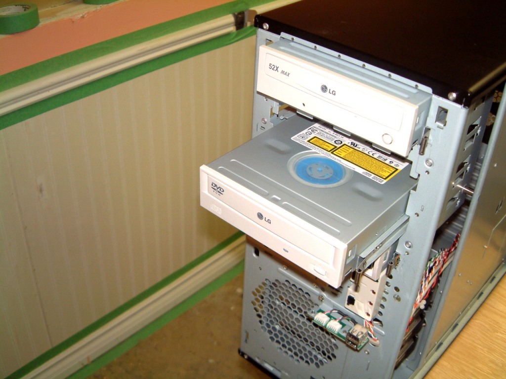
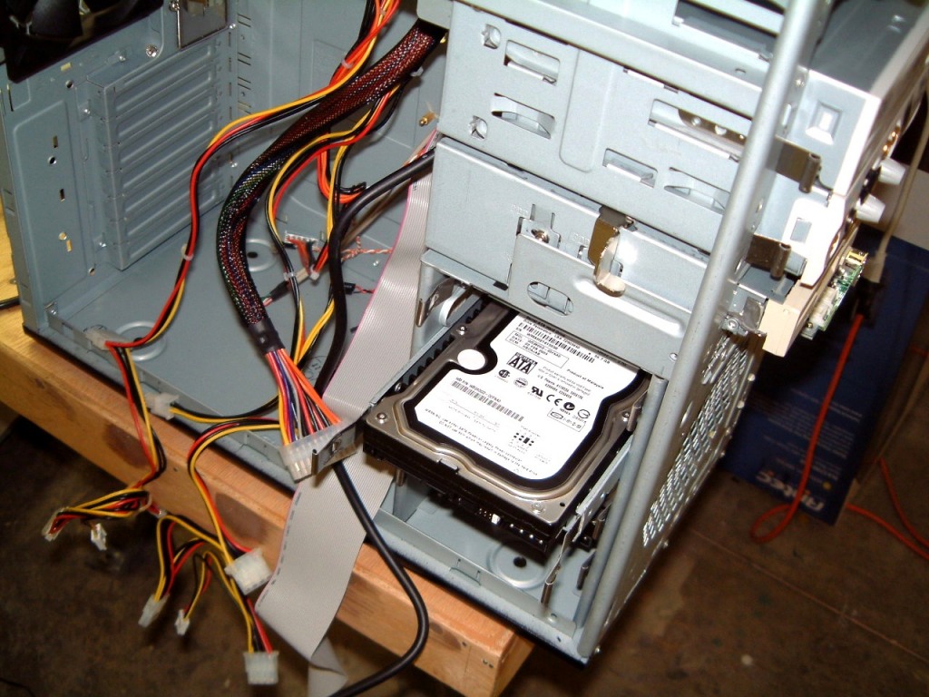

However, I decide to swap the tapered ends of the side-rail. Eureka; when I switch around the ends, everything slides into place! Simple - once it's done.
The WD drives are quite heavy. But. perhaps a 3/16 th inch piece of steel on the top of each of the HDD's - held in place by a thin piece of rubber carpet tape, will add more mass to the HDD, with a slight-amount of mass isolation. This will deaden any vibration. There is another fix that I can do if it is needed. In order to further reduce drumming of the case bottom, I can add an eight-of-an-inch of high density foam to the inside of the case bottom. By trimming it down, it will fit neatly. If more air circulation is still needed, I can always use a 'nibbler' to create clearance for a couple of two-and-a-half inch holes in the bottom of the case. There are some small exhaust fans that can be added providing that four one-and-a-quarter inch high rubber feet are added underneath. The needed wires can be run thro' the case bottom. A small piece of filter material can be added to prevent entry of debris into the case itself. The fan chassis is stiff enough to reinforce the bottom. I hope that these acoustic fixes wont be needed.
July 17th, 2004 .
I finally found the time to do more work in the new 'server'. Installing the Mobo was a bit of a hassle as the spring-finger-loaded RF shield was very tight. However, the Antec case was a perfect fit. All the brass screw-in spacers fit the mother board well. The ATI card locked-in perfectly. Ever the RAID controller was easy to place, however we has to place it one slot further away from the ATI cars for proper air circulation.
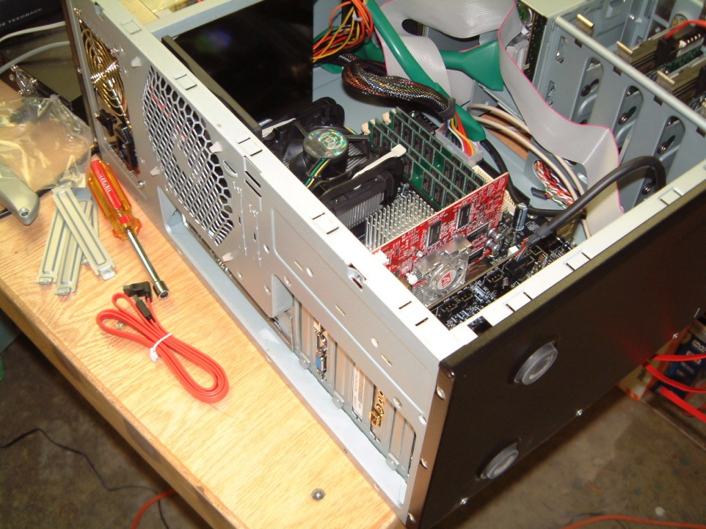
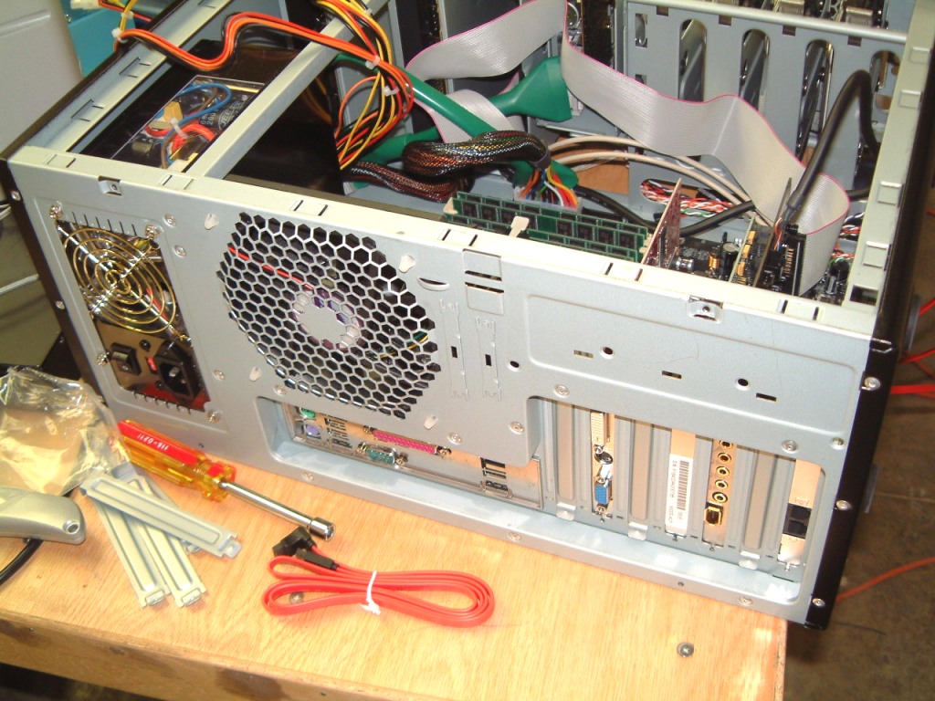
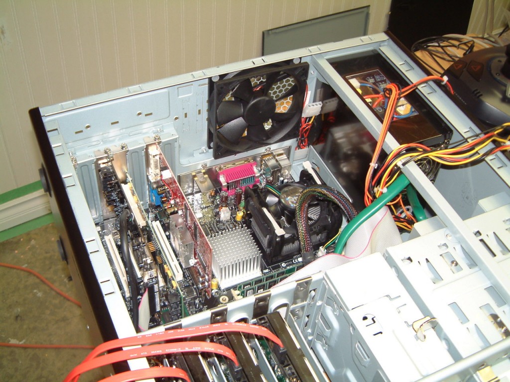
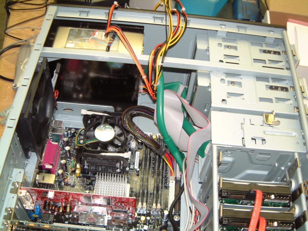 I have taken some photo's of the case
with only part of the job completed. When it is completed, more shots will be
added along with some comments.
I have taken some photo's of the case
with only part of the job completed. When it is completed, more shots will be
added along with some comments.
July 18th, 2004
The new server is finally finished and tested! It was quite worthwhile! Here is what it looks like now. Having a clear side panel on the case wasn't a requirement even though the power supply is lit up. As I can play DVD's with all the detail would could wish (the ATI board is great), this is simply an extra.

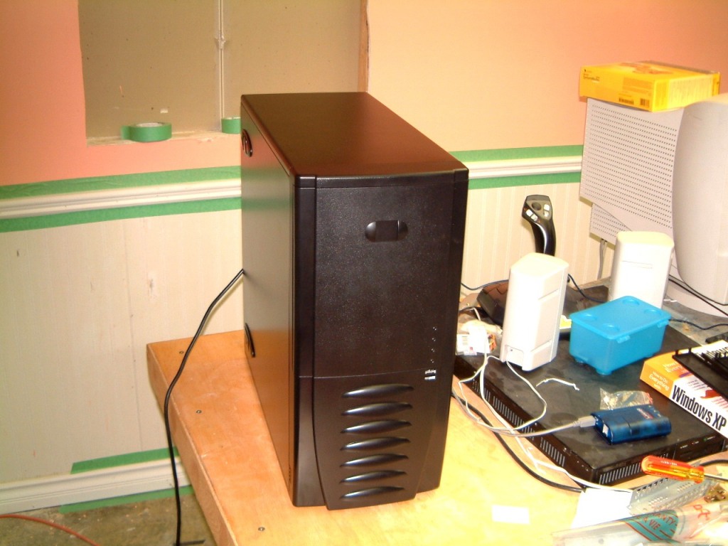 I was too apprehensive
about the noise and vibration, especially as the speed is so high. I need not
have worried, for it is very quiet. I will run it for thirty six hours
before I place and connect it to the rest of the clients. I have to
re-integrate it with WidevieW.
I was too apprehensive
about the noise and vibration, especially as the speed is so high. I need not
have worried, for it is very quiet. I will run it for thirty six hours
before I place and connect it to the rest of the clients. I have to
re-integrate it with WidevieW.
July 26th, 2004
Still working on the Flight Simulator - we had to delay the work for a week as we were overloaded with orders. Our copier couldn't be serviced as one of its parts was discontinued. As a consequence, it took us two and a half weeks to sign a purchase contract. One thing at a time seems to be 'old hat'.
This might be another classic example of multitasking failure. Major corporations have embraced it to promote efficiency and raise corporate profits. The result is that there has been a major increase in stress, absenteeism, re-stocking problems and an increase in serious errors. By eliminating the older employees (who were paid more) and promoting the younger staff (who were more inclined to work for lower pay), these corporations are starting to see a gradual decrease in profitability.
The corporate solution is usually mergers. This too often results in a major increase in the pay for the CEO's, increase in their perks', a substantial increase in their stock options, at times, coupled with 'creative' bookkeeping. Only now, some smaller corporations are beginning to question the so called 'benefits' of multi-tasking.
Remember, that in the middle 80's, Microsoft's claimed that the 'paperless office' was at hand?
July 27th, 2004
It seems to be the time to reorganize, once more. The #?$*@# shop is now too crowded to work efficiently. There are several things that have to be sold as there are some items that are better suited to what I am doing. The older overhead saw takes up too much room and is cumbersome to set up. It may be ideal for smaller-production-runs, but the newer twin rear rail arrangements seem to work better and are better to use.
To give you an idea of what I am talking about, here is a general view of the 'back shop'.

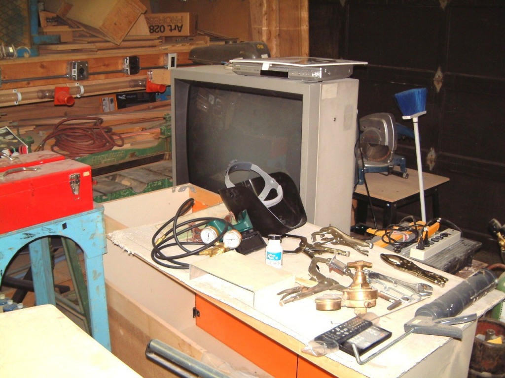
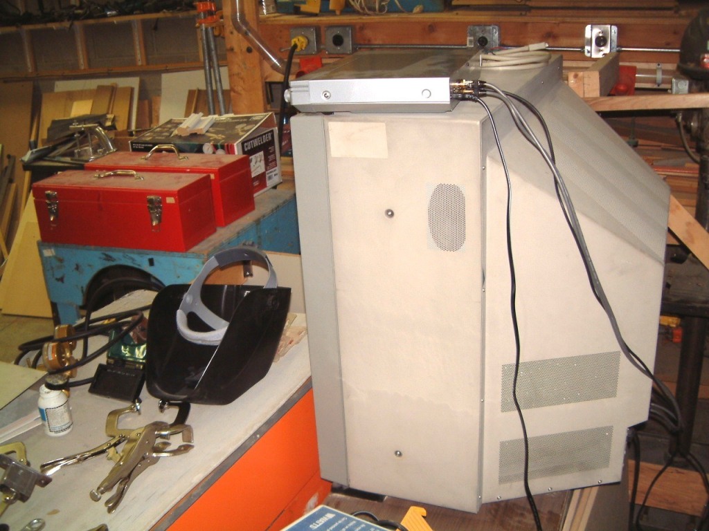
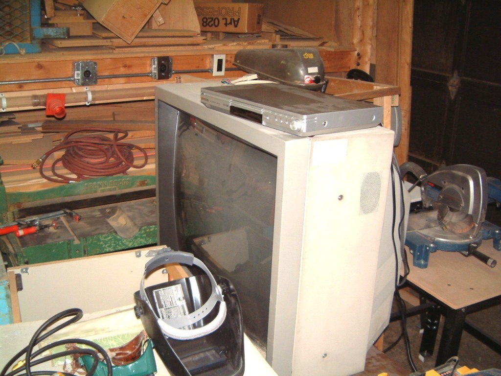
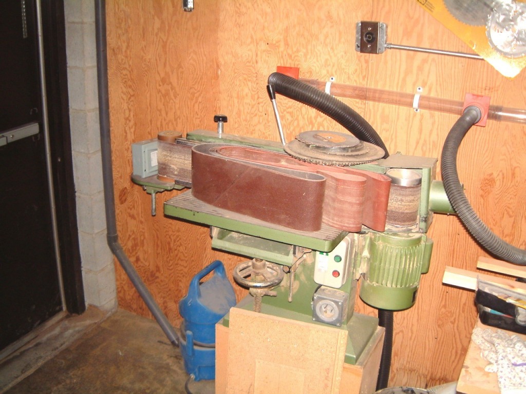
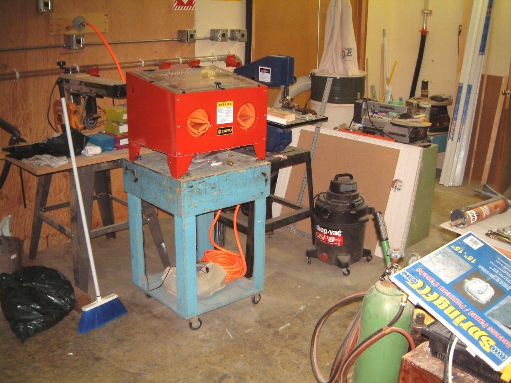
We tested the new high resolution 'server' at noon today and it behaved perfectly, when flown from the keyboard - this is much more difficult to do than by using a yoke and pedals We tried it with the maximum settings for the update time, as well as shadow details and dynamic scenery. As we expected, the clients, were constrained by 'slewing mode' couldn't show the same benefits - but they didn't seem to matter.
I can't wait to transfer the four other 'client' computers to the new table. I ran all the electrical power cables in advance so now, I'll move all the three newer 'client' computers with the 'server' where they are already on the new table up to the front, where the other five computers have rested since last fall. As you know, the old 'server' could not operate under direct X-nine. Even though four of the clients are running Win 98 -'2nd Ed' they are stable. We already have an ATI download for the ATI 'rage' cards. I am still hunting for the older video DRAM modules. As the ATI cards in the HP Pentium two computers seem to have separated the fifteen pin connections from the mouse, keyboard and LAN connections even though they are all on a common metal plate, the only way I'll know, is to disassemble an old scrapped HP computer and see what's inside. I might have to do the same operation to the ATI card on the Pentium 2 on the Compaq computer. I can see just enough to know that there is a video DRAM receptacle on the card. However, this card is almost impossible to extract from the MOBO. I attempted to contact ATI and gave them the names of the two companies and the model numbers of the computers involved.
However, now service inquiries at ATI are almost as bad as Microsoft. I am really pissed-off at having to fill out a lengthy form twice (for each computer manufacturer) and then receive what is obviously a 'boilerplate or generic reply'. Don't they realize that if a customer has to spend over an hour to compose a pertinent e-mail, that I might be intelligent enough to deduce, from the content of their reply, that ATI do not seem to give a damn. When I sent them the two e-mails, I had already supplied all the information that they now requested that I supply. I still wonder whether any tech ever reads the entire e-mail before composing a reply? Freudian slip? I was about to say 'composting' a reply!
I began to use ATI cards in 1989 and the joke was, at the time, the drivers
seem to to change on a weekly basis. It was so frustrating to me, that for
three years I switched to Hercules Graphics cards. Our office was, at one
time, just north of Highway 7, less than a quarter mile from ATI. I
still had one a computer with an ATI card. It would crash on me twice a day.
When I called ATI, and told them where we were, the said to drop off the card
and they would check it out. Three days later, they called us and said that the
card seemed to be OK. I had taken the precaution of making a small scratch on
one of the chips (using a grounding strap - of course). The scratch mark was
not there. OK, the board didn't cause any more problems after that.
.
More, later.
August 5th, 2004
I took everything off the old table (the one with the broken castor - even IBM ditched it. Feeling as if I had lost an old friend, I replaced all four castors and now its being used to move odds and ends around the shop)
So, I finally moved the new table, and fit it near the Flight Simulator Console screen array. The photo shows the 'Spotter Plane' view - on the departure runway at Buttonville airport. It took over five hours until I had a 'sort of' Flight Simulator running on the 'server' with three clients. I found that I had a collection of LAN cables - seven inches is too short and thirty six inches is too long! Perhaps I can find others that are less than sixty four inches?

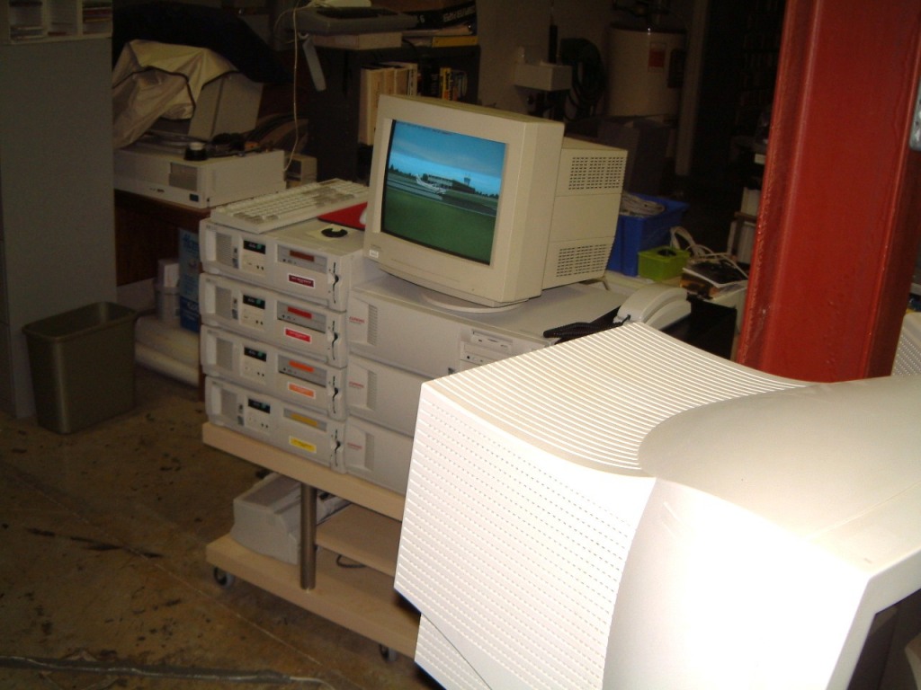
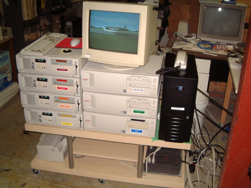 This will give a better idea of the computer set-up, needed for eight views.
The rear angled views are not there - yet, as I still have to finish the two
steel stands for the monitors. The limit was reached at 9:35 last night. We had
an old desk in the rear shop that we were going to use for a database master.
It ran Win 95 and was going to run Foxpro. This was not done as we were
overwhelmed with new orders. So I was faced with an unexpected demand to
move the old (and heavy) desk out with the equally old nineteen inch Electrohome
monitor and the old '486 computer. It took over five hours until we had the
desk upended on a wheeled cart and by the loading dock. (It is now the sixth of
August) So, drenched with perspiration, at 5:00 I had to run the Jacuzzi as I
was too stiff to walk!
This will give a better idea of the computer set-up, needed for eight views.
The rear angled views are not there - yet, as I still have to finish the two
steel stands for the monitors. The limit was reached at 9:35 last night. We had
an old desk in the rear shop that we were going to use for a database master.
It ran Win 95 and was going to run Foxpro. This was not done as we were
overwhelmed with new orders. So I was faced with an unexpected demand to
move the old (and heavy) desk out with the equally old nineteen inch Electrohome
monitor and the old '486 computer. It took over five hours until we had the
desk upended on a wheeled cart and by the loading dock. (It is now the sixth of
August) So, drenched with perspiration, at 5:00 I had to run the Jacuzzi as I
was too stiff to walk!
August 12th, 2004
All the designing and fabrication finally paid off. All the 'client computers' tracked the 'server' with ease. Even when one of the 'client' machines had its AC power cord accidentally unplugged, when it came on line once more, it resumed tracking the 'server'.
I could not resist buzzing the CN tower (at a higher altitude of course). Here is a view of it with the cockpit
removed. 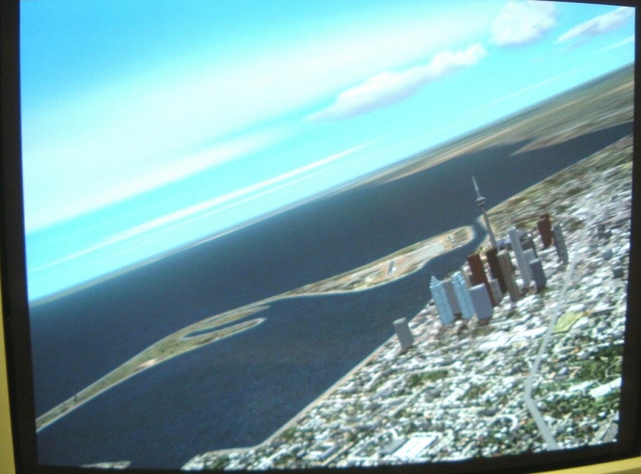 The photo does not show the incredible
view as the tower is circled! I'll show what the 'pilot' sees in the five
monitors that I can capture (the photo's are blurred because I didn't have the
room to use a tripod). The following shots are with the aircraft in a moderate
bank about 4:13 in the afternoon. The cloud's are moderate, a typical afternoon
when the base must be about 2000 to 3000 feet above the Cessna 182 RG.
The photo does not show the incredible
view as the tower is circled! I'll show what the 'pilot' sees in the five
monitors that I can capture (the photo's are blurred because I didn't have the
room to use a tripod). The following shots are with the aircraft in a moderate
bank about 4:13 in the afternoon. The cloud's are moderate, a typical afternoon
when the base must be about 2000 to 3000 feet above the Cessna 182 RG.
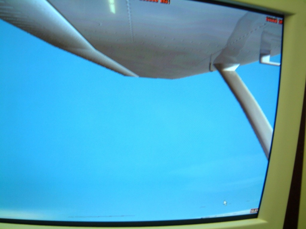
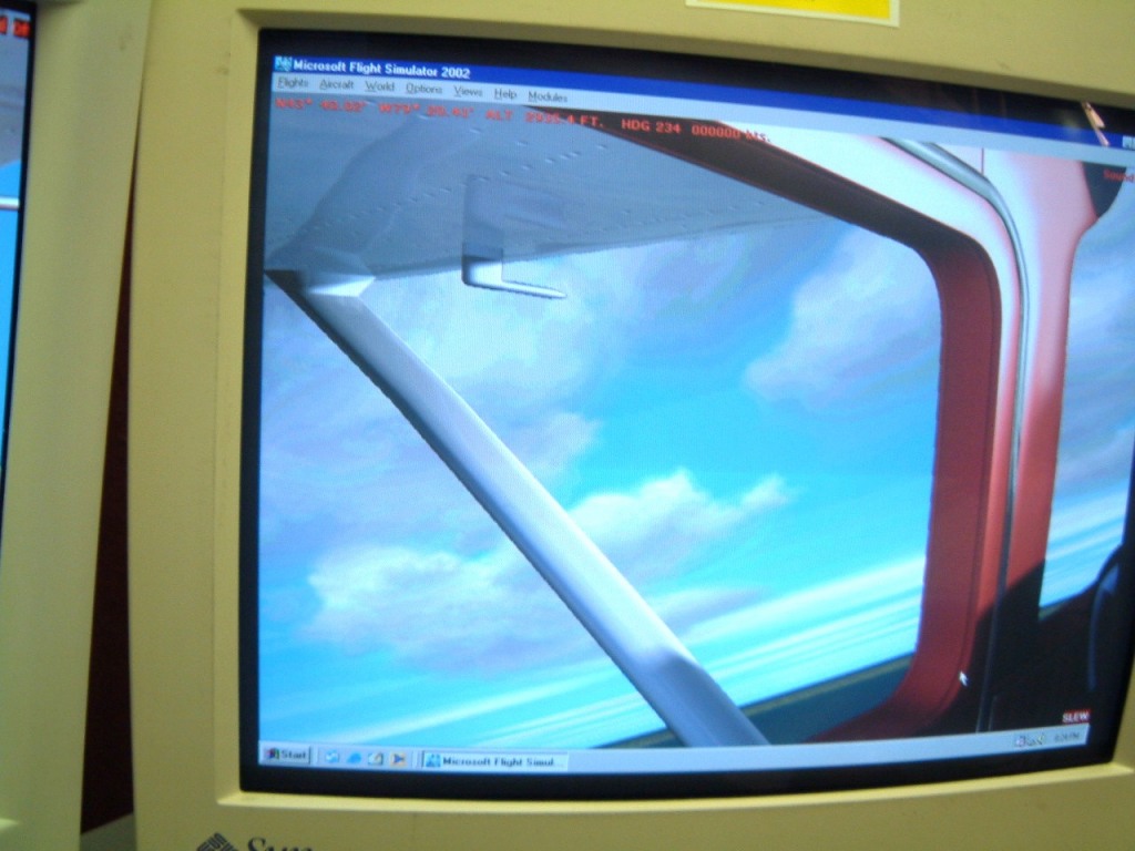
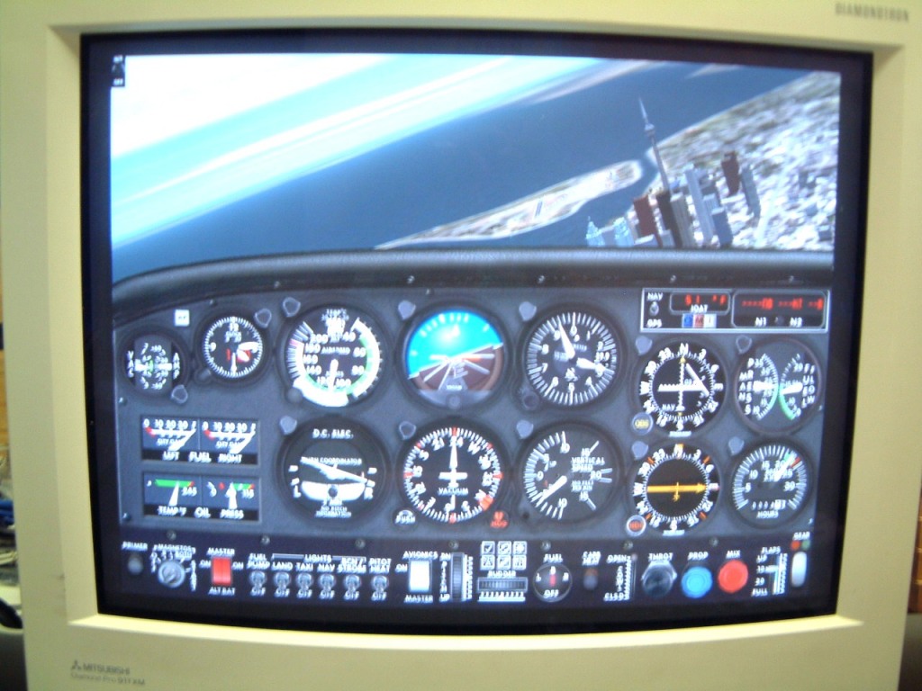
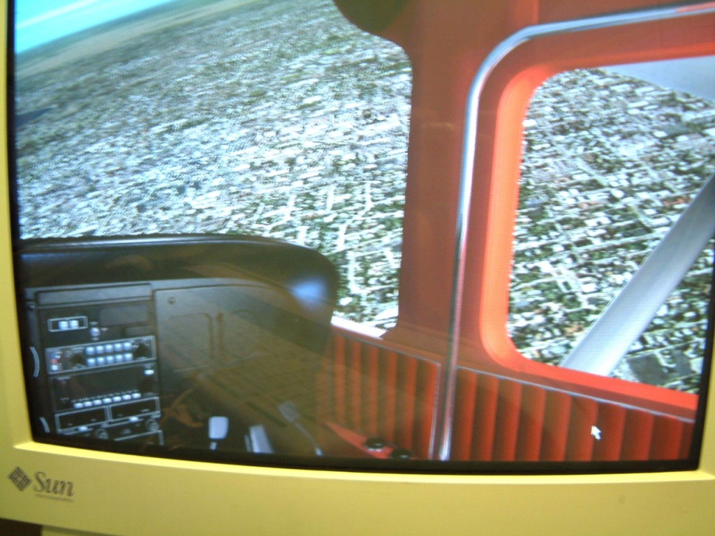
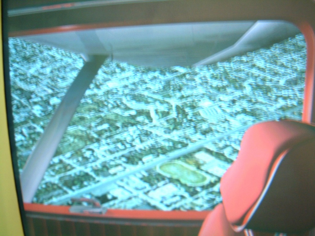
The sequence should be obvious. Once again I have to assure people that these photo's are blurred because (for obvious reasons) I could not use a 'flash'.

As these are 'static shots', there is no sense of motion. I have found that if the flight simulator is used in a darker environment in the shop, the sense of actual flight is vivid; reinforced by the apparent motion of the scenery. It is even more striking at lower altitudes!
Now, the realism of low altitude flight is quite dependent on the scenery that is available for the location of the flights. A low level flight over Toronto is great such as it is, however the actual ground simulation lacks 'real' detail, for example, the wide that seems to begin at some place on the Don Valley Parkway then this 'avenue' running south west by west does not exist. However, Las Vegas, in the late evening, is striking, especially when the flight contuse over the Hoover dam.
As I mentioned, I have flown my own Cessna 182 from Buttonville, westward thro' the Sarnia area, landing at Port Huron to clear US Customs. Then, I'd head towards Kalamazoo, then south westward to land at Valprasio Indiana, south to Champaign. Then, continued to the north of St Louis to finally land at Kansas City Kansas for the night. Early, the next day, I flew just north of Denver, landing at Jefferson for a top-up of fuel. Then, I headed southward to the Colorado Springs area, to cross over the Sangre De Cristo Mountains, to land at Alamosa for coffee. Then I headed Southward towards. After refueling, I then headed to Gallup, New Mexico, then over the Zuni Reservation, onto Show Low. Thence, to fly over the Salt River Canyon and westward just south of the Roosevelt dam. From there I continued westward to follow the northern part of Superstion Mountains. I finally landed north of Phoenix, at Deer Valley Airport.
I sometimes flew northward over the Mongolian Plateau passing Sedona, Flagstaff, passing the San Francisco Mountains, up to the Grand Canyon National Park Airport where I'd land for fuel. On takeoff, I'd receive clearance for a flight path along the Grand Canyon, (at that time it was legal to fly about 1000 feet above the canyon rim), then past Tuba City along Black Mesa, south of Mexican Water continuing eastward, heading either to Shiprock New Mexico or to the Window Rock area.
Sometimes I'd land at a small airport near Four Points (I hate to admit it but I don't recall its name). I had made a habit of shopping for 'pawn'. In the middle 1990's, there was more available at reasonable prices.
I would generally head up to Colorado following the fight I'd taken earlier.
When I can find the time, I'll attempt to re-create my flights using the Flight Simulator. You have to remember that even though I can accelerate the time for a 'virtual flight', appreciation cannot be condensed that much. I am told that there are a host of 'add-ons' compatible with FS 2002, that can run from a CD-Rom providing the buffer memory is large enough. However I don't know if the will run under RAID 5.
One problem with MS FS 2002/2004 is the transition between 'special scenery' clips and the more generalized 'airport specific scenery'.
I finally found a piece of software that allows me to capture the screen of anything running Flight Simulator. I use (Control+F12) to capture it to a file (under My Documents - (ScreenShot~~)). Here is the first one.
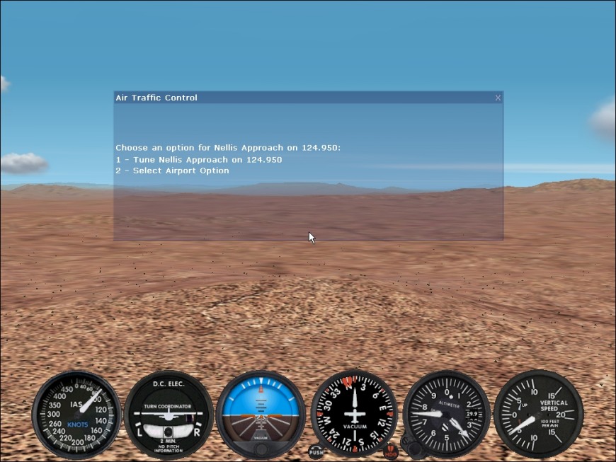
This is the first one. The capture software must be loaded onto every computer, eg., the server and all the clients. For now, I am using floppy disks and transferring the shots to another computer where I can file them. It's cumbersome, but it works.
It comes from Gadwin - PrintScreen - Version 2.6 Build 782. This shot is on departure from Henderson Exec in Nevada which is why the Nellis Approach is on the screen. In this shot I've used "W" to remove the full panel from the screen.
I found that it was necessary to replace the Cirrus Logic video card that the HP used with an ATI video Cards on the 'clients'. This increased the video memory to 16 Meg. That was enough so that they could use the graphics acceleration. The Cirrus Video card pooped out in both in Win 98 and even more in Win 2000: fortunately, ATI made a 32 MegRage 128 PCI card that the HP computer 'saw' when the card was plugged in and the computer re-started. With the Cd-Rom inserted, the configuration went OK. These older cards generally run about $70-80 C. The card on the Compaq was also a problem.
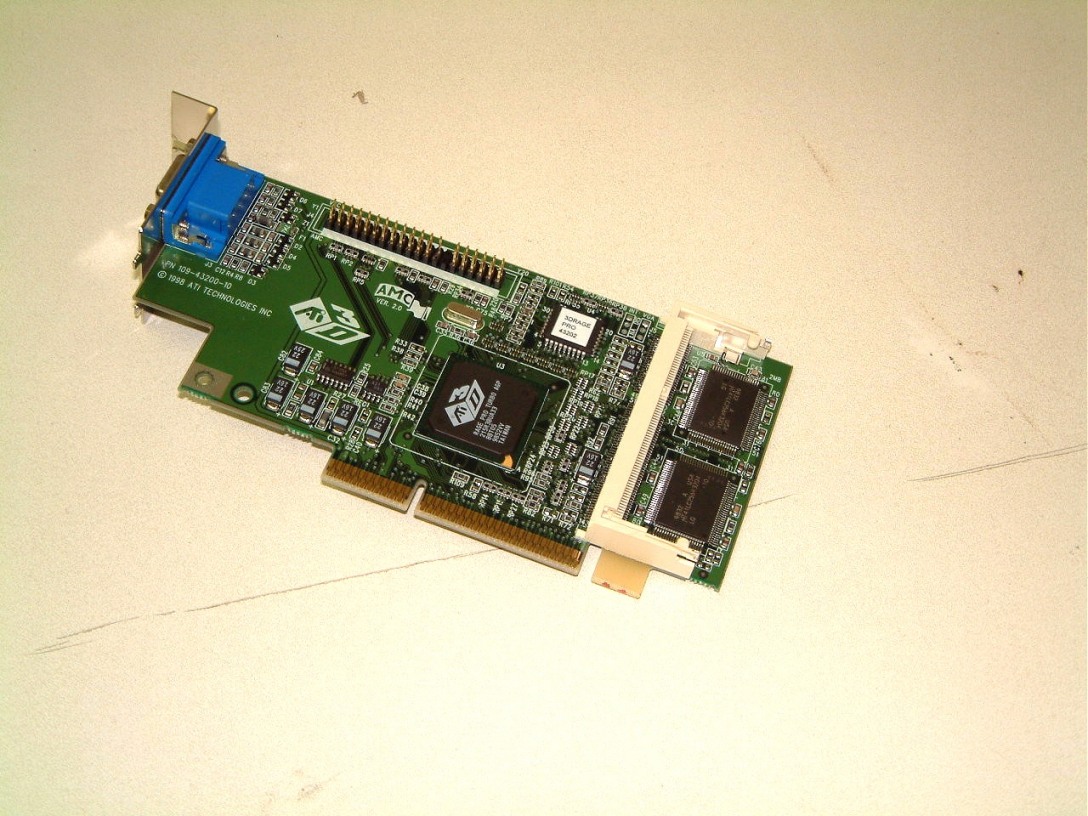 We contacted ATI to see if the plug-in memory expansion mini-card was still
available. It is as you can see an AGP 2 card.
We contacted ATI to see if the plug-in memory expansion mini-card was still
available. It is as you can see an AGP 2 card.
There is another possible addition to the plethora of computers I an now using. Might I possibly use a GPS (Shift+ 1 to 9) on a 4" x 6" LCD color screen? Shades of Garmin!
Other jobs had to
be done before I could do anything more on the Flight Simulator. I have to jump
back in time to put everything into context.
February 18th, 2005
I was so PO'd at some if the technical staff (now in Montreal PQ, rather than Milton, ON, as we were receiving as many as fifteen worms a week, I documented over a dozen of the ones that I intercepted on my wife's computer. Beside having an updated firewall and an antivirus software on her computer, we pay extra for our ISP block this stuff. But it wasn't until I raised hell before they cleaned out their servers. We haven't had a similar attack after January 16th, 2005 (a week after I mailed the documentation to Montreal).
We elected to remain with a 'dial-up' connection even though it was slow, because having your address 'changed' each connection allows much less time for a hacker to 'plant' a 'nasty' on your computer. We use Ad-aware and SpyBot search and destroy, in all of our computers as we do not want 'data-miners' type infections on any computer.
For these reasons, we avoided a DSL connection until we could shut-down our computers each day. This way, if any computer was infected, we had a 'minimal-resource computer' as a back-up waiting to take over.
I dislike running Cat 5e LAN cable as nobody likes to 'fish' the wing through the space over the 'suspended ceiling'. Even worse, is having to remove the inter-drywall fiberglass insulation to use a 'fish-tape' to probe and pull a taped-up' LAN connector vertically through the drywall. But, there is even more. The insulation has to be replaced with an excess and such openings that had to be made, patched. Here is a typical example of an installation.


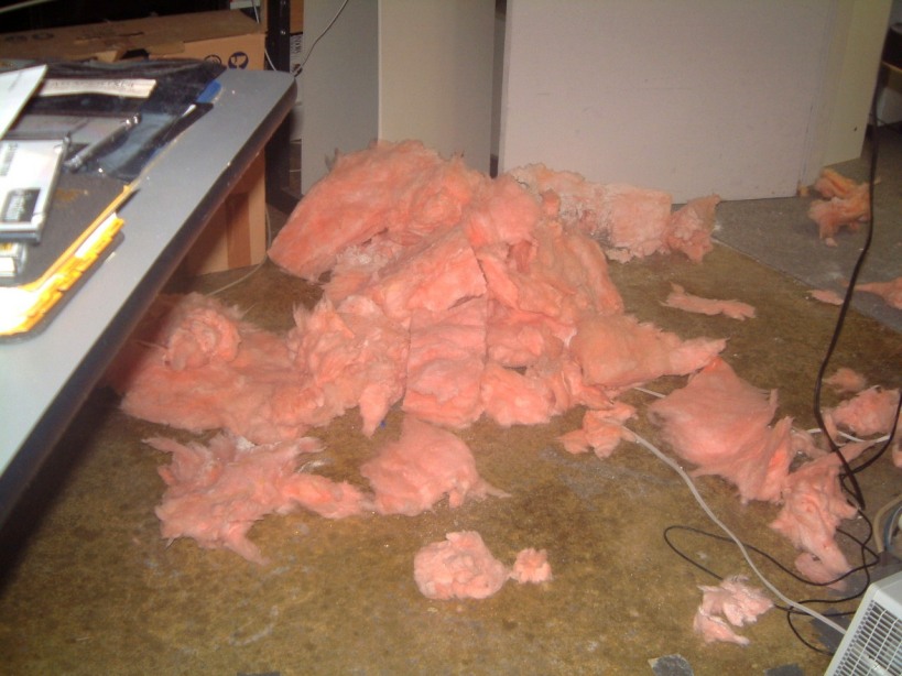
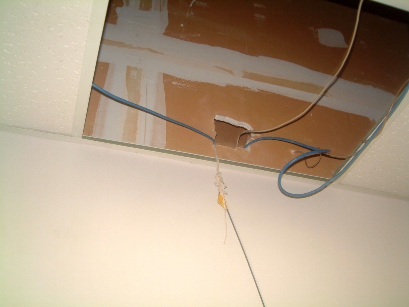
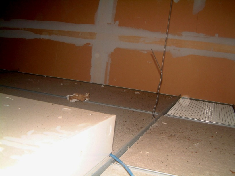

But, the finished connection at the other end of the LAN cable makes it worth the trouble.
April 5th 2004.
I was stopped abruptly when I attempted to buy fine sand so that I could sandblast the various bits needed for a keyboard tray (which has to be mounted on the left leg of the Flight Simulator 'wing'). It seems that fine sand has it's own MSDS. Which is fine if you are going to buy 40 Kilo's. But, I need about a kilo at the most (the last Kilo bag lasted me five years). However, sandblasting (even out doors behind the plant, is now verboten. I was forced to obtain a closed system glass frit 'blaster'. I thought that silicosis was silicosis no matter what you contracted it.

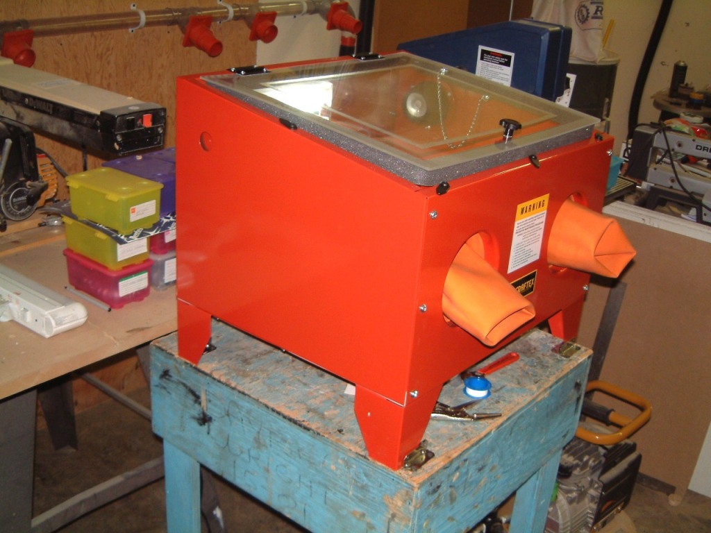 I bought a
closed-system 'frit blaster'. It took five hours to assemble as it came as a
kit. The gloves took over an hour to stretch over the front inside-lip of the
device. Here is a photo of it (with the gloves not yet fitted). Now I have to
find a suitable castored table of the correct height and hook it up to a valved
source of compressed (unlubricated) air. OK, I located one that was
ideal, (the Shot on the right), as it has a shelf that can support a fifty-foot
length of air supply hose.
I bought a
closed-system 'frit blaster'. It took five hours to assemble as it came as a
kit. The gloves took over an hour to stretch over the front inside-lip of the
device. Here is a photo of it (with the gloves not yet fitted). Now I have to
find a suitable castored table of the correct height and hook it up to a valved
source of compressed (unlubricated) air. OK, I located one that was
ideal, (the Shot on the right), as it has a shelf that can support a fifty-foot
length of air supply hose.

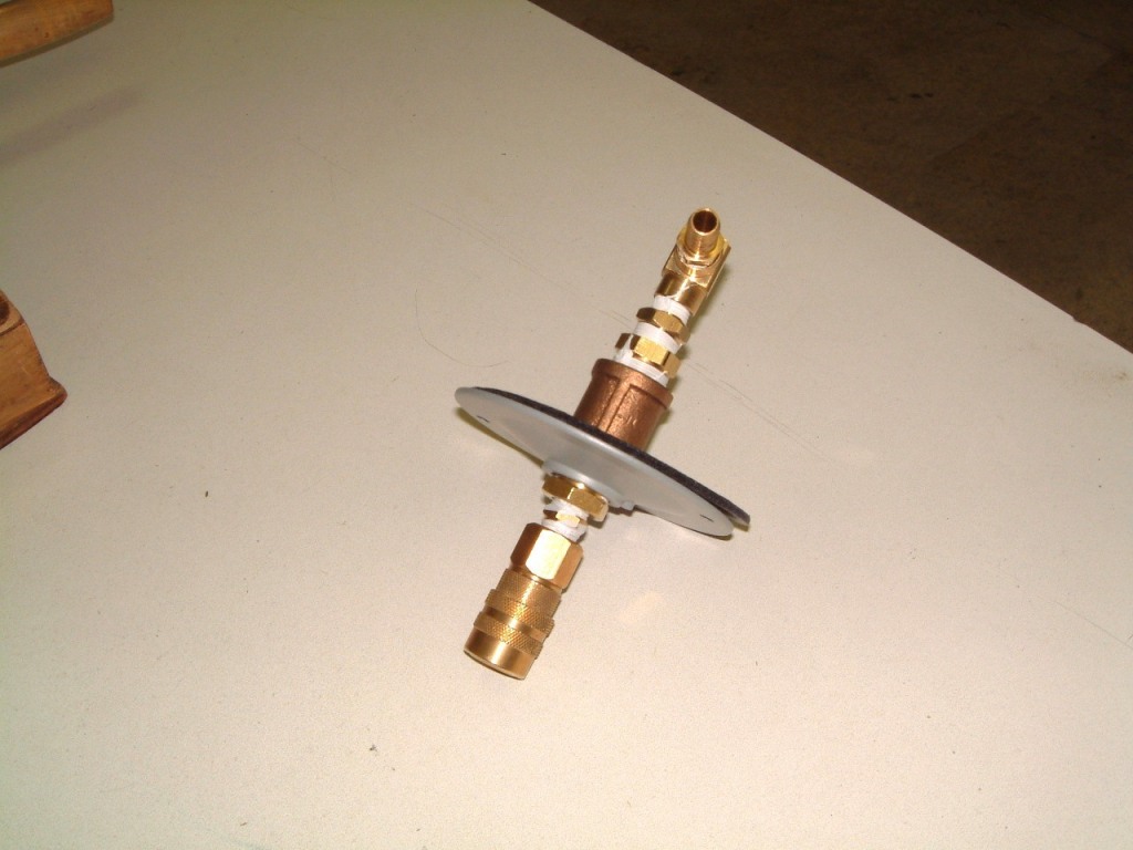
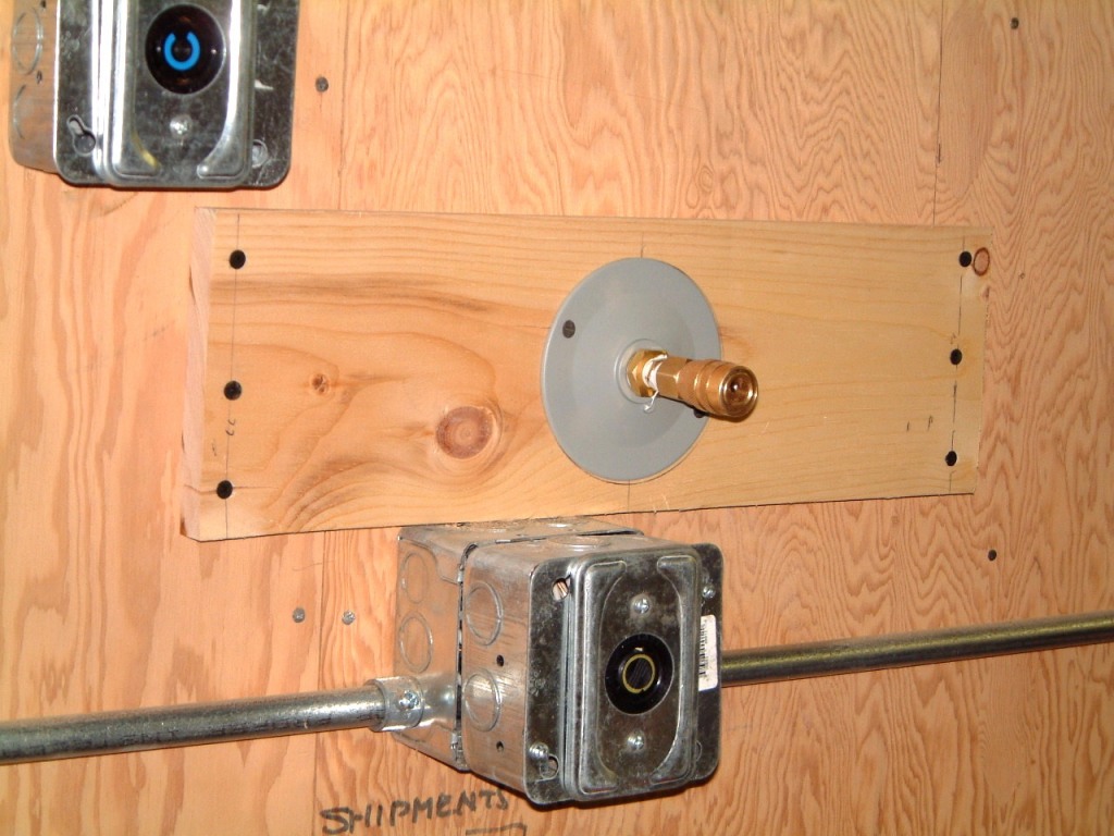 As you can
see from the shot, I had to use a flanged electrical fitting to fabricate a
secure mounting for the compresses air connection. To the right is the final
wall-mounted piece of pine 1"x6" - 17 1/2" I used to bridge the
wall studs so that I could install another Compressed-Air outlet in the
Carpentry Shop The Use of several 1 3/8 th flat headed drywall screws makes it
easy to place the compressed-air outlet in a location with very little
working area. I decided to make several more of them as I also needed one in
the machine shop area. For this outlet I used a coiled hose on the
connector where the plate was placed to bridge two rafters. I restored one of
Leigh's wheeled cabinets (the shot on the right) so that I could mount the frit-blaster
on the top. However, I definitely must move the chip/sawdust collector
out of the carpentry area. There is always another problem that stands in
the way. Now I have a heavy cabinet (loaded with heavy dies) just where I have
to re-locate the dust collection system apparatus! There is an added hitch, the
blower fan is not exactly quiet so that I will have to make a vertically hinged
enclosure with sound absorbent material on all four sides. The opening at the
top will need only a expanded metal screen capped with a HEPA filter. The top
opening is about 22" x 36".I have been using this same dust
collection system since 1985 and it is quite efficient, but noisy!
As you can
see from the shot, I had to use a flanged electrical fitting to fabricate a
secure mounting for the compresses air connection. To the right is the final
wall-mounted piece of pine 1"x6" - 17 1/2" I used to bridge the
wall studs so that I could install another Compressed-Air outlet in the
Carpentry Shop The Use of several 1 3/8 th flat headed drywall screws makes it
easy to place the compressed-air outlet in a location with very little
working area. I decided to make several more of them as I also needed one in
the machine shop area. For this outlet I used a coiled hose on the
connector where the plate was placed to bridge two rafters. I restored one of
Leigh's wheeled cabinets (the shot on the right) so that I could mount the frit-blaster
on the top. However, I definitely must move the chip/sawdust collector
out of the carpentry area. There is always another problem that stands in
the way. Now I have a heavy cabinet (loaded with heavy dies) just where I have
to re-locate the dust collection system apparatus! There is an added hitch, the
blower fan is not exactly quiet so that I will have to make a vertically hinged
enclosure with sound absorbent material on all four sides. The opening at the
top will need only a expanded metal screen capped with a HEPA filter. The top
opening is about 22" x 36".I have been using this same dust
collection system since 1985 and it is quite efficient, but noisy!
There is another item that I have to use in the shop. I used to have a TIG welder The unit was 'lifted' from the plant in 1985 when we were at the CES show. For some reason (I do not understand) the roll-down loading dock door was left open when our staff (at the time) were standing in the parking lot (at the front of our plant) having a smoke). (we NEVER permitted smoking in our plant).
There are always more things that I have to organize, such as: I needed three metal stands. I have a Ryobi miter saw that has been resting on a small table for several years. It seems to used at least every two weeks - in spurts. Then there is a metal cutting saw using a carburundum blade, It has to be dragged out of hiding every time I I have to fabricate something that has to be brazed or welded. Home Depot had the stands I needed. One will serve for the TIG/MIG welder.
I had forgotten just how many metal bolts and nuts are involved. When I opened the bag, I found found out I have to locate my (folding) welding screen; I remembered moving it up to the North 'mezzanine' over the parts 'stacks'. I used to keep it facing the loading dock door. I'll have to cut up pieces of stone board and screw them (horizontally) to the inside of the door.


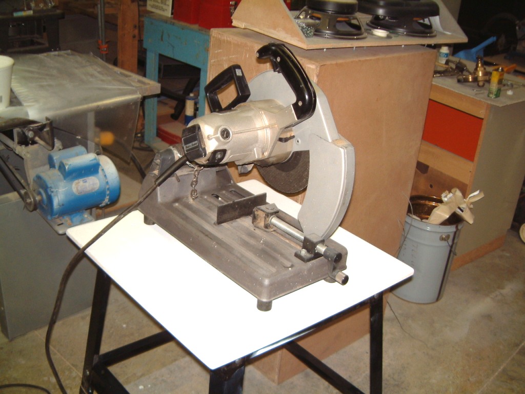

The shot on the far left was taken about two years ago ( I think about January 2001 when I was installing the dust system), you can just see the wooden table (from the Media Room where it supported DW SPA preamp since 1988). This is the first item that I transferred to a new stand. It still has the masking tape label stuck on the black enamel painted steel. The next picture is another Home Depot stand. Because I will use it for cutting metal, the medium density board has several coats of heat-resistent enamel. The next one is with the saw, in this case, rather than being bolted down, its feet are recessed 3/16" below the surface. In the event of a fire, the saw can be lifted from the surface (and placed on the floor) so that any hot or burning material cannot get trapped under the saw itself. The next shows the Black ? Decker 'chop saw' in the top of the metal stand. Next, is a Lincoln Electric TIG welding unit. It can be converted to a MIG unit, but I am still waiting for the last piece of the setup; the solenoid valve was missing from the kit.
I will have to make some curved hangers for the cables and hoses. I can drill a couple of holes in the frame and attach an horizontal extension. Then I can braze a curved hose/cable support in place.
I have an accumulation of minor jobs that seem to accumulate ever time I take a day off. Sometimes, I have the feeling that there ia a secret repository where they get together and breed. What were nine jobs when I took a day off, seem to be twenty-six the morning after. I have often wondered whether there is some inverse (preverse) linkage to the price of gas?
Recently, (March
18, 2004) some people that were looking here, have been a bit skeptical
about what I am doing. To give you some idea of where some of where the
computer work is taking place, here is part of my 'back room'. The first shot
is two stacked Compaq Pentium 2's being converted to Win 2000. The hard drives
are 80 Gig Western Digital, that replaced the 6 Gig 'client' computers. In
both, the memory is now 2x256 Meg. There is another one on the upper shelf on
the steel frame 'burn-in' shelves that is undergoing testing before adding a
new FS 2002.
Next one is a Pentium 3 with Win XP. I am checking a Logitech joy stick. This took several hours of frustration and re-booting before we were able to USB port to recognize the device. It is running on a former Gateway unit where I phantomed over to a new WD 80 Gb hard drive.
The last shot shows the chaos resulting when several computers have to be built in too small a working space.
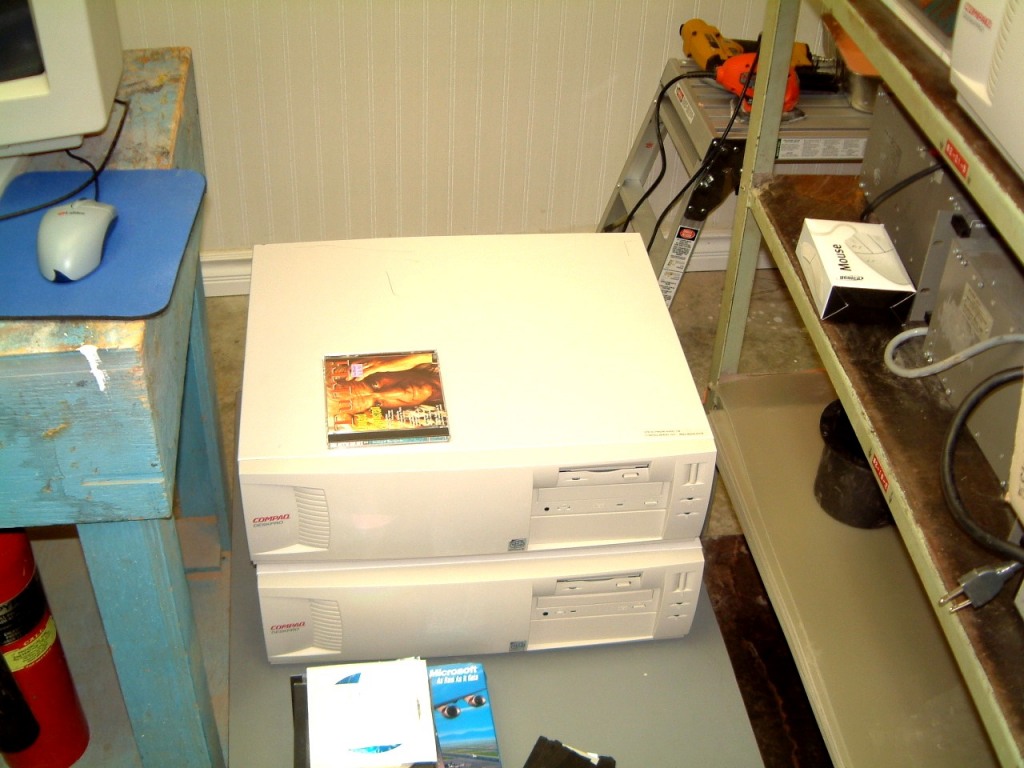
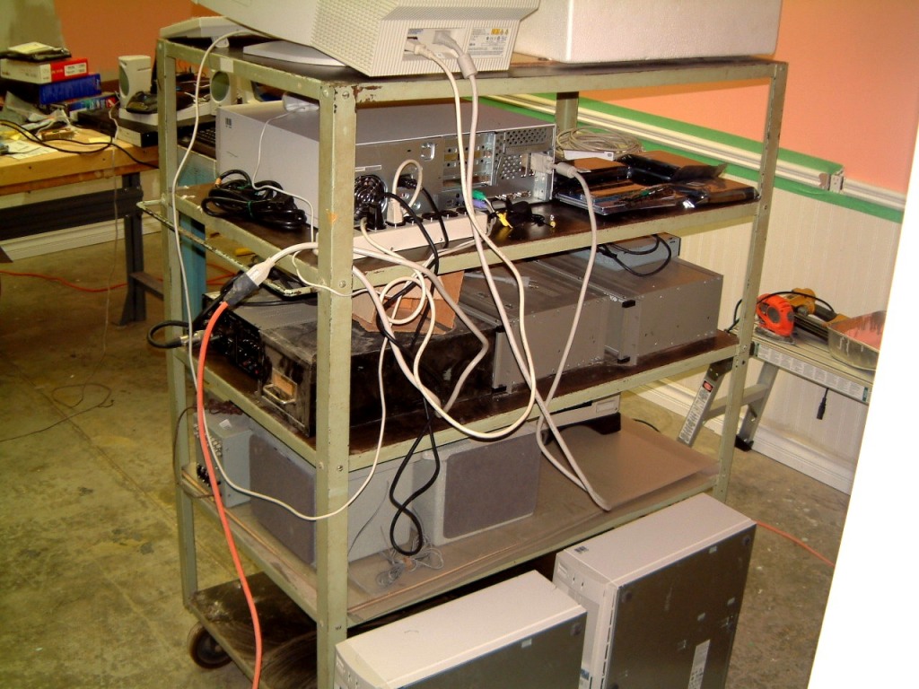
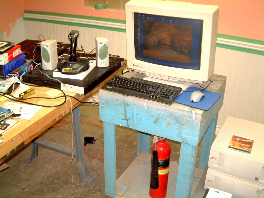
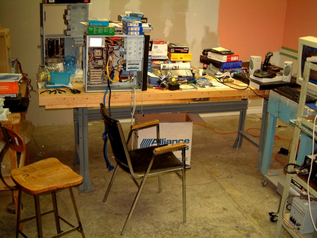
Yes, the second shot shows two Compaq Pentium 2 computers that will be used for the Rear Right angled and Rear Left angled Win 98 Flight Simulator setup. The completion of the keyboard mounting is waiting on the delivery of a small acetylene cylinder. When it arrives, I can complete brazing the keyboard support. There is only one location that seems logical, attaching to the support for the left 'wing' leg. There is enough room available beneath the KDM switch.
Now, I have to make a centered combination keyboard and mouse pad, where I can reach them while seated.
I can just imagine a 'panicky pilot' attempting to bail-out and attempting to lift 800 pounds of monitors + the whole set (150 pounds) of audio stuff + heavens knows what else; off the floor! I remember all too well, a LearJet co-pilot who had been over-relaxing too much, feeling the foot pedals sliding on the carpet as he attempted a hard left bank to land the plane with severe cross-wind (about 80 knots) that 'broke' thirty feet above the runway. 'Nuff said'.
I can't wait to set-up a pair of 'David Clark' headphones. I have already pre-drilled a replacement yoke' for a microphone button. The next addition will be a 'coolie-hat' switch for trimming. I made a casting of an old yoke after enlarging the ends, but haven't machined it yet to accept the switches.
I am still looking in my cartons of war-surplus (Korean) stuff as I know I have some small lights (not eyebrow type - the panel has built-in membrane switches) and I am sure to hit a wire if I attempt to drill there. In the '60's when I was rallying almost every couple of weeks, I found some war-surplus 'map lights' that were on flexible stalks. As they were two bucks each, I bought twenty four. I kept a dozen whem I moved back to Canada. I used two of them in my Cessna 182 and squirreled the rest away. No, I mounted four of the lights under my Schober Classical Organ to iluminate the pedal board, so I have to have six left. The problem is that I have accumulated so much 'neat stuff' over forty years, even though I get rid of 'stuff' once a month (and kept an inventory every six months), so much had to be relocated when we needed space, we had to hire a couple of students to help us. However, they moved so much without keeping track of where they moved it to, that I am constantly being surprised when I find things that I thought had been accidentally discarded.
There will be more items that may reflect needed improvements. Real soon now - as it were!
Several people have asked me to post some of the shots of the older DOS based Novel Twist 360 Flight Simulator. Here is a start.
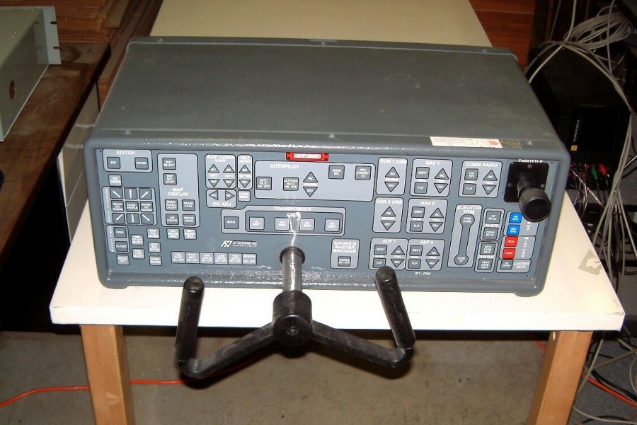
I didn't add that I had been building an ATC radar simulator at the same time as (in 1988) we had planned to take the original Flight Simulator to Comdex. I managed to get it ready just in time. But, we didn't have enough space in the minivan. It was too late to lease a step-van. There was an additional drawback. If I used my minivan it wasn't considered a commercial vehicle. But, I'd already been dinged at several weigh stations to procure documentation (for a fee) so that I could continue through the State.
Here is a couple of shots of the ATC simulator. There is a bit of a problem with the speech recognition engine accepting the pilot in the Flight Simulator 'voice reply'. Remember that the ATC Radar simulator is over fifty feet away from the 'pilot' and is not in contact with the airport control tower once the tower releases him from the control zone. In a zone where it is under ATC supervision, the radar controller takes over. A problem that has bugged me is the creation of a shimp-boat with the call sign of the aircraft on the flight simulator itself.


Another problem, was that I had set up the Flight Simulator in the office on Leslie Street, and our plant (where I had the ATC Simulator running) was several miles away. Not an easy thing to do when you have to debug both simulators at the same time!
February 16th, 2004
Another jump back in time. A major bug had me #*!%*(^$ (very irate) as only some of the controls seemed to work the way they should. All the membrane type keypads were OK, and the throttle, propeller and mixture were fine. The 'real' switches were also OK. However only the brakes worked. After much head scratching, I realized that the RF signals from Buttonville Municipal Airport used to drive me nuts whenever I had to take a computer out of its case for service. What if.....the connecting cable to the foot pedals is quite long...what if it was picking up an RF signal and rectifying it do to a dirty connector? As this connector is on the rear of the NT Systems case, it's not easy to access. It was worth a try! I dug up my handy bottle of Stabilant, got down on my knees and unplugged the connector. It was gold plated, however it was filthy beyond belief.
I remembered at the time that the roof on our plant was stripped and re-tarred. The *?$*#( roofers pulled out all the furnace stacks and then used some leaf blowers to clean off the debris. Too much of it wound up (or down as the case was) inside our plant. We spent over a week cleaning up. We are still finding bits of roofing debris in unexpected places. We also had to bring in our own furnace contractors to reseat the heating vents that were damaged during the roof repairs.
I think that you are beginning to get the picture. Even though the Flight Simulator and Console were covered over with heavy poly-vapour barrier sheeting, we still had to clean up the floor several times (We had to have the roof vents checked for damage every time that the roof on an adjacent unit had to be fixed).
Sure enough. the connector looked as if had been exposed to a sort of a roofing tar condensate. OK, first clean off the goop; them apply Stabilant. Re-connect it again. Re-boot the computer. Eureka, it worked! The rudder and ailerons work. The long unshielded cable was picking up RF and the crud on the connector was acting as an RF detector. Now to recalibrate the NT Systems console. (you probably guessed that I'd try it out first. Well, even without the re-calibration I was able to take off, fly a circuit and land the Cessna 182! (With Some Difficulty). I traced the fault to the cable that connected a serial (Comm 1) port the 'Modem' connector at the rear of the flight simulator. As one of the 'Right' computers seemed to have an installation fault, I brought in the technician who had installed the larger hard disk drives. (I have got used to using a grounding strap on my left hand. the wire usually runs op my left sleeve and I have several banana jacks that I can easily use whenever I am using the NT simulator. As I mentioned, we used an earlier model at trade shows and never had a problem in having anybody ground themselves before the used it.
But this time I had a problem. The panel on the Flight Simulator uses 'membrane switches' on the panel. These are very sensitive to static discharges which is why I tell, even service technicians, to ground themselves BEFORE they use a membrane switch. Therefore, I was stunned when, even after he read the manual that emphatically states that if you don't ground yourself, you risk frying one of the the controller chips in the flight simulator.
By now, you have guessed what happened. When the internal computer in the NT 361 simulator is turned on, the power light flashes three times. This indicates that the computer is operating correctly. Even with a bad serial cable connection, it flashes three times.
However, I had turned off the power supply to the NT 360 before I ran the communication installation disk. I had switched to a longer serial communication port cable. When the technician arrived, he said that he had read the part of the manual that pertained to the cautionary notices as well as setting up the comm port. He switched on the NT 360 and pressed one of the membrane switches before the power light began to flash. It lit steadily and my heart skipped a beat.
Complete disassembly takes more than a full day, and reassembly tales two to three days as every connection has to be checked. Before we take it to a trade show, all the parts are pre-arranged on 1/4 inch wide masonite strips to ensure that everything fits. All connections are labeled and or color coded. We ensure that all connecting cables have Ferrite Snap-On RF traps (monitors, audio, mice, keyboard, AC for all the computer power and we use the largest uninterruptable (battery back up) supply that we can move around. As we have another computer which has a simulated radar unit for ATC, we have mapped all the nav-aids as well. We never go online at these shows (we use a null-modem to connect the NT 360 to the ATC computer) - (with the usual snapon ferrite RF suppressers).
To move all the monitors off the upper desk we had to get a set of IKEA legs to fit an old IKEA table. Everything went OK. We trimmed 2" off the length of the legs so that we could use castors (IKEA had run out of legs with castors). But, when we attempted to screw the legs onto the pre-mounted flanges, nothing fit. It took me three hours to decide to use a depth micrometer to see what might be the problem. IKEA uses pre-threaded cylindrical inserts to assemble their stuff. Usually, it is a reliable. But, in all four of these legs, the cross-hole was a sixteenth of an inch too shallow. For good measure I increased it to an eighth of an inch. It worked.
See photo (we haven't moved
the monitors yet).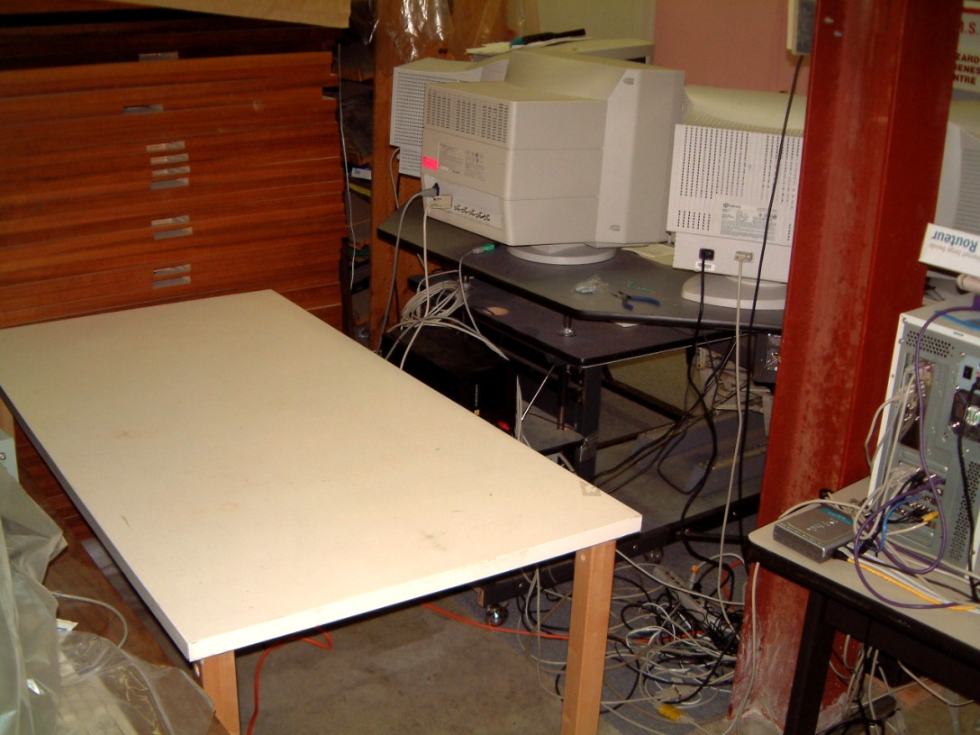
I have decided to mount the larger Front Left and Front Right speakers (a
little too heavy for screw-in anchors) by the use of 1/4" NFT Flat head
Allen screws. (we have over two thousand left over from the production of
ESL's.
This was written in late February 2003 when I was still coping with Wideview 2002! In case some perspicacious reader sends me an e-mail, advising me that there is a AGP board that allows three views - the Matrox Parhelia - about $550 US) with three (Analogue - RGB) outputs that can 'divide' the image into three parts. This allows them to retain the dynamic graphics on all three outputs. Unfortunately, the board will only operate with Windows 2000 or XT. The latest 'Info' from WidevieW is there is a 'Wideview 2004 version up and running - OH GOODY it runs best on Pentium 4's for the 'server' and Pentium 3's for the 'clients'. It seems to need Flight Simulator 2004! Another four or five grand for Bill Gates!
I was aware of this board and when 19" flat screens drop substantially in price, and Pentium 4's get faster still (and the CPU chips drop to $350) I will consider it's use. However, I am sure that Microsoft will come out with FS 2005 or FS 2006 1/2 and, perhaps, require a new Microsoft Operating System to use it, I will wait. I still have reservations about the detail on LCD and Laser diode displays - not only because of 'burn-in' but the compromise in switching.
April 11th, 2003.
I finally got sort of 'secretaries' typewriter desk (I used one to carry the 39" Mitsubishi monitor that I used to demonstrate (in the field-in 1994) when I had enough 'warm bodies' to carry the whole set-up into the demo-room (and, hopefully carry it back to the rental truck - what do you think? I had to pay outsiders to carry the stuff back out).
Finally, all five computers will fit on a rugged steel frame (sort of a typewriter desk or a desk used to support servers). I can stack the four Pentium Two's as the cooling fan airflow exits at the side of the low cases. The main computer that operates as a host for the LAN connected servers is (currently) Pentium !!! in a vertical case. (I was appalled at the cost of all the cables that were needed for the hook-up)! Can I organize everything; with lots of color-coded tags so that the whole 'scmere' can be taken apart and hooked up again? Does someone make stacking keyboards let alone stackable mice? It is more and more akin to playing three dimensional chess! (I'm making fun or didn't you guess?)
I located four Maxtor 40 Gb hard that were Manufactured for IBM - at least, that's what it said when I looked up the parts numbers - I learned a long time ago to run a Due Diligence Typesearch; these are drives that I can use to upgrade the servers.
On WideView Links Page, there are some very elaborate cockpit designs several of which mimic real layouts (more or less). I gave to say that my mind was boggled at the cost of some of them! Sure, and the cost of many of these layouts is less than 4% of a clapped-out '747 and the fuel is much much less expensive. But?????
Now, to change
the subject, I have also been asked, what I have used for the sound system. I
had some experience with the Creative Inspire card 5.1. All I needed was
two front channels (left and right), two rear channels (left and right)
and the sub-woofer. I used larger speakers in the front, with the smaller
Cambridge Soundworks at the rear. There is a separate power supply to which is
connected to the power amplifier. This is contained in the case for the
sub-woofer. That might not be enough bass for a student's hard landing, so if
you'll look below the photos....
There are both audio and digital cables along with a front-rear and volume control.
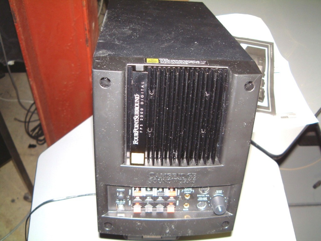
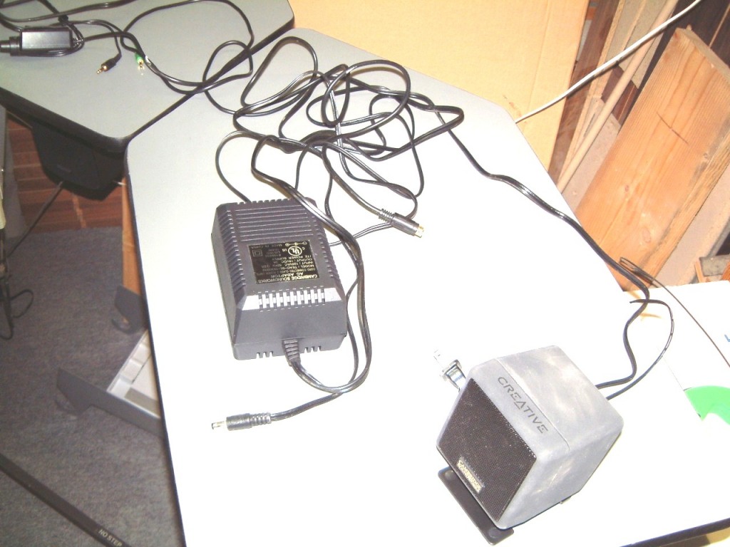

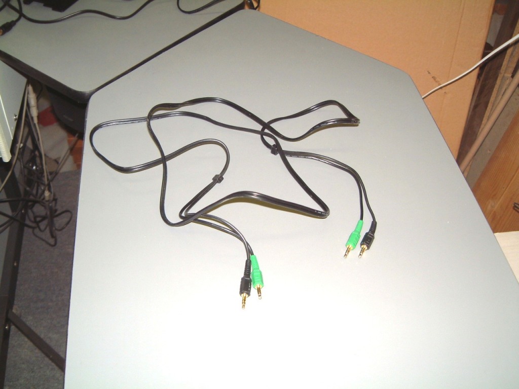
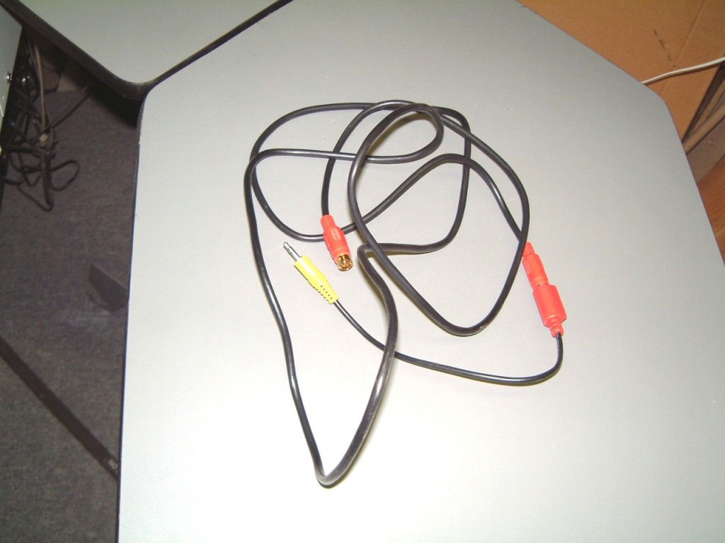
Note: one of the smaller speakers is to the right of the transformer.
As I said. I finally decided to use was able to squeeze a Stanford Acoustics TM-4 TREMORS that will be screwed down onto the space between the mounting rails for the pilots seat. I have an old twenty-five watt mono power amplifier that I can use.
To make it in order to make it comply with air reg's, I might install a full shoulder harness that I may use with the simulator. I can add a David Clark headset/mike to intimidate the would-be pilot! I am waiting to see the reaction ogf the first pilot that is strapped down with a full shoulder harness thats wearing a DC headset with microphone when he crashes! I used to do it at trade shows using a LearJet MS FS program with a slow screen refresh rate. I realised that on 'Flying a simulator' they react more unexpectly when they screw up, than less trained pilots. The exerienced pilots tend to loose it; I think that because the usual controls are not where these pilots expected them to be, they over-react. I have seen several LearJet pilots (they flew their bosses to the LasVegas shows) and being gadget inclined, any booth with a Flight Simulator drew them like flies to sugar!
I'm sure that I'll b forgiven if I seem to jump back and forth too much. The reason is that I am receiving e-mail from people that wish to know how the various 'projects' are going. Therefore, I sometimes have to post a photo to this web-site to make it clear. The problem is that these questions are not in a logical sequence, and I don't have the time to retype and reorganise everything.
More on FS 2002, I downloaded Wideview 2000 from:
and can't wait to get it running, however I will have to add more stuff! You have to download two more programs fron the same source; QickGOTO and Key2Mouse. All are in zip format. Caution! Be sure that you download the approriate software!
I had to buy Symantic 2002 as I didn't want to download Microsoft's Internet Explorer to upgrade to Norton 2003.(the on-line uprgades - as do Norton's Firewall (Symantec).
I have four extra copies of MS Flight Simulator Pro 2002 which is enough to use the existing Pentium !!! All in Wonder PRO Radeon AGP card running Win 98 (as a Pentium 4 system) as a master. I will loose the dynamic scenery in the four slaves which is no great loss.
I remember when, in 1988 we trundeled the old FS Desk System to CES in Las Vegas in our Dodge minivan.
On subsiquent shows in the Toronto area, we used the "wings" to hold hand-outs and samples of Stabilant. Now, even though the display breaks down for shipping, the mere thought of lugging five 19" or 21" monitors (packed for shipment) still boggles my mind! Even the thought of carrying four extra computer's is daunting enough without the four 19" CRT type monitors! I do wish that I could justify the use (and cost) of LCD type monitors; as these are MUCH easier to lift!
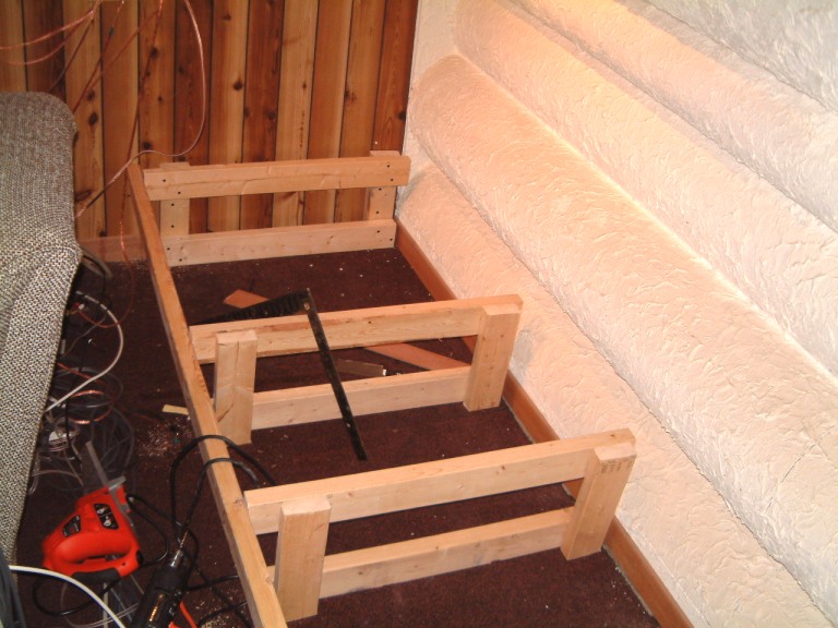
This is the beginning of the platform. First, I made ten supports - I had to use some badly twisted wood that I bought three years ago. It seemed fine at the time, but when I started to use it as studs, I noticed that it was beginning to twist. I put it aside, intending to use it as short fillers on the corners, but there was too much of this crap. I intended to scrap it, but much later, it had dried, twisted but stable. Ideal for the platform! This shot shows the series of frames. But, so much for the ten frames I planned, by the time the frames were lined up, side by side, the wracking, forced me to discard five of them. Even so, I had to add fillers at the sides of two of them.
The first and the last are spaced on 32 inch centers to allow clearance for the tilted sub-woofer panels. I decided to mount the sub-woofers to a half-inch-thick piece of medium-density board with some cross-bracing inside the enclosure. Remember, the sub-woofers are mounted with their magnets on the outside. I used pot-metal E-Z ANCOR imported by ITW Construction Products, Toronto, Canada as Paulin # 6411. The #10 size has to be re-tapped so that a #10 x 24 metal screw will fit, as they come with a sort of sheet metal screw. I relented, and will mount these sub-woofers with eight #10x24 filister head metal screws. I will run a bead of silicone around the perimeter of these drivers. By mounting them on the outside, there is another benefit, the holes for these sub-woofers can be a little smaller (providing that they don't cause a problem with the suspension clearance).
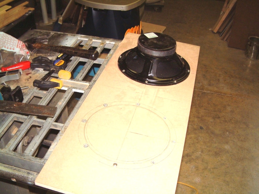

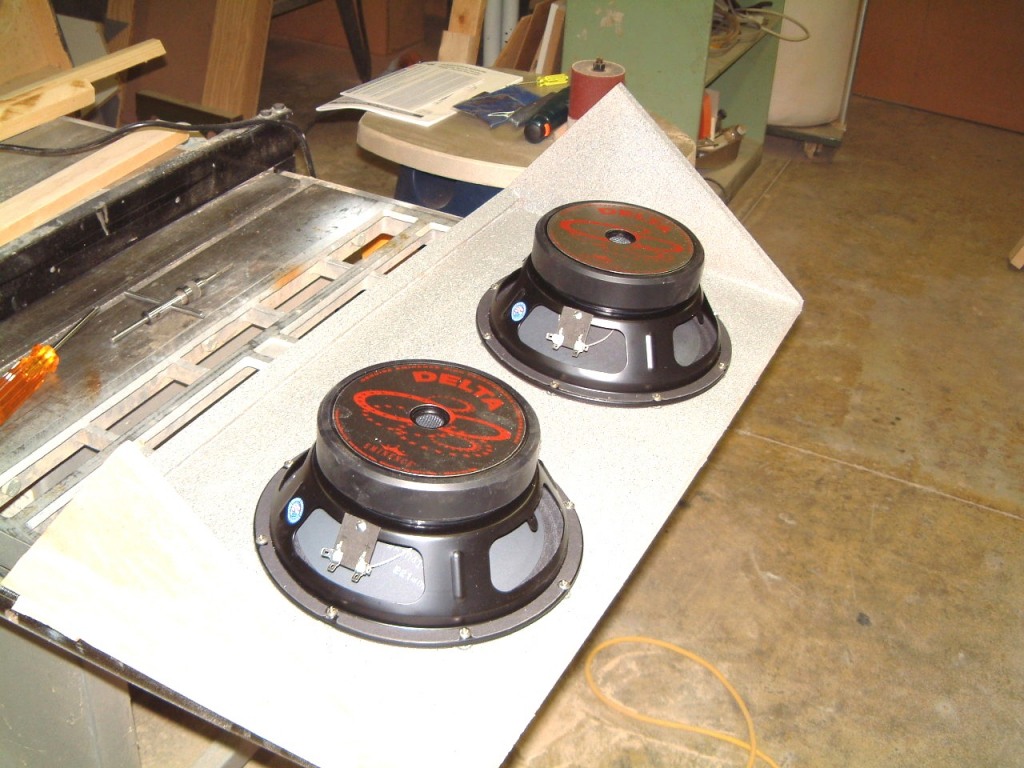
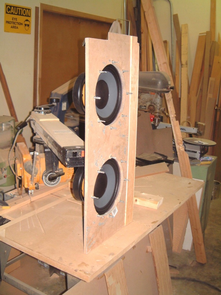

I finally decided on a ten-inch 300 watt RMS sub-woofer using a 56 oz., magnet and a 63.5 mm voice coil. this will give me a capacity of 1,200 watts (which ought to pop the screws on the platform). Now, (perish the thought), if I blow a sub-woofer, I can replace it much easier than if I had to crawl inside the enclosure! I used black plastic bushings at the wall edge of the platform (in the front of the sub-woofer). I also ran a piece of 3/4" ABS pipe through to the other set of sub-woofer connections (in the other compartment of the platform).
February 23rd, 2005
After a prolonged delay while I was running new LAN connections, I saw that I had to complete the platform at the rear of the madia room in order to place a new Cat 5e LAN connection on the east wall. But in order to cut a hole for the plate, I would have to complete the platform. As I hadn't completed the four sub-woofer installation, this would force me to get-on-with-it. As I may have noted two years ago, some of the 2" x 4" were twisted. The worst were at the western end of the platform. Installation of the sub-woofer panels at the eastern end of the platform was relatively simple. But, at weatern end; well, you don't want to know. Suffice to say that I had to make a fresh set of frames. Then, I was finally able to install theother sub-woofer panel with little problems. In order to make the long rear secure, I had to glue on the rear panels by using LoclTite panel adhesive, and plenty of clamps.
We had to retain a consultant to complete some of the work..
Fortunately, we were able to locate a seemingly tireless assistant. 
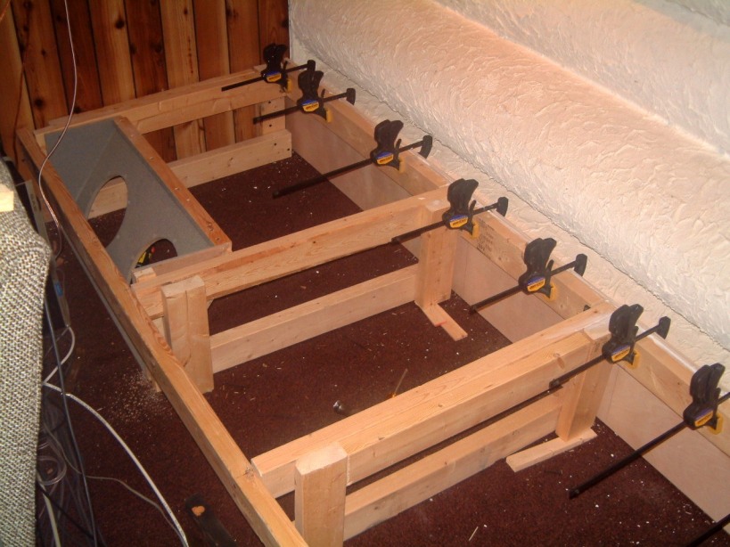 You can just see the eastern sub-woofer panel finally in place. The vertical
rear panel is on and the top is level with all the frames. However, I think I
will allow the adhesive to set before I attampt more. The temperature in the
room is about 60 degrees (F) today so there is no need to push it.
You can just see the eastern sub-woofer panel finally in place. The vertical
rear panel is on and the top is level with all the frames. However, I think I
will allow the adhesive to set before I attampt more. The temperature in the
room is about 60 degrees (F) today so there is no need to push it.

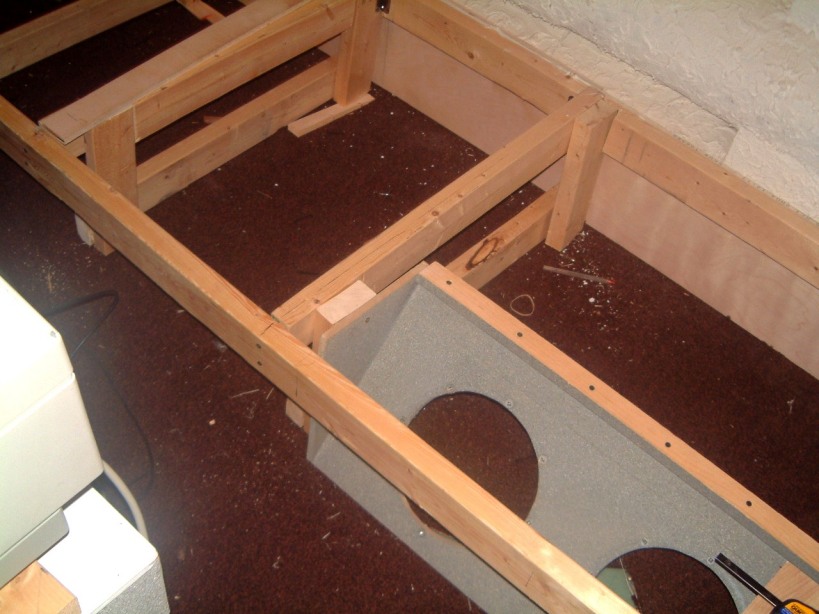
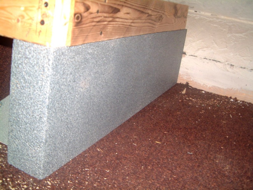
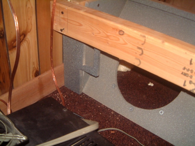
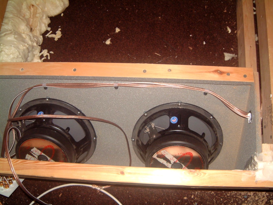
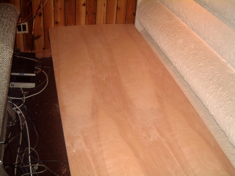
Two days later all of the clamps have been removed; the front has been added (this fits between the sub-woofer panels). The left photo shows the inclined panel for the two sub-woofers; the next shot shows the inclined panel at the other end of the platform. This too has mounting holes fpr two more sub-woofers. The next photo shows the west end of the platform. Note that the carpeting was left in place. I will use silicone adhesive to glue the horizontal pieces to the carpeting The divider has not been put in place as several more pieces have to be cut. (eg, the top of the of the center pieces are still open and the east end of the platform is still open to the wall). The next shot shows the openings for the west pair of sub-woofer. The next photo shows how the heavy-gauge wiring to the far pair of sub-woofers used three nylon clips to route the wiring over the sub-woofers. A plastic bushing was cemented to the medium-density board and solicone as used to seal the wiring in place. There are two small openings that can be sealed with pieces of 1" x 2" that is glued to both the upper edge of the front panels and both glued and screwed to the 2" x 4" rails supporting the frames.
The last shot shows the top of the platform in place for marking where all the parts will be located.
Some additional shots are included to illustrate some of the extra connections that were added. The left one shows the four sub-woofer terminals. The next photo is collection of terminals on the wall of the media room Centered at the top is the LAN as well as the cable TV connections. Below these are three plates, the two left side ambience speakers, the center speaker over the screen, and the two right side ambience speakers. Then below these. are two plates. The left one is the four connections to the two sets of loudspeakers located at the back of the media room.

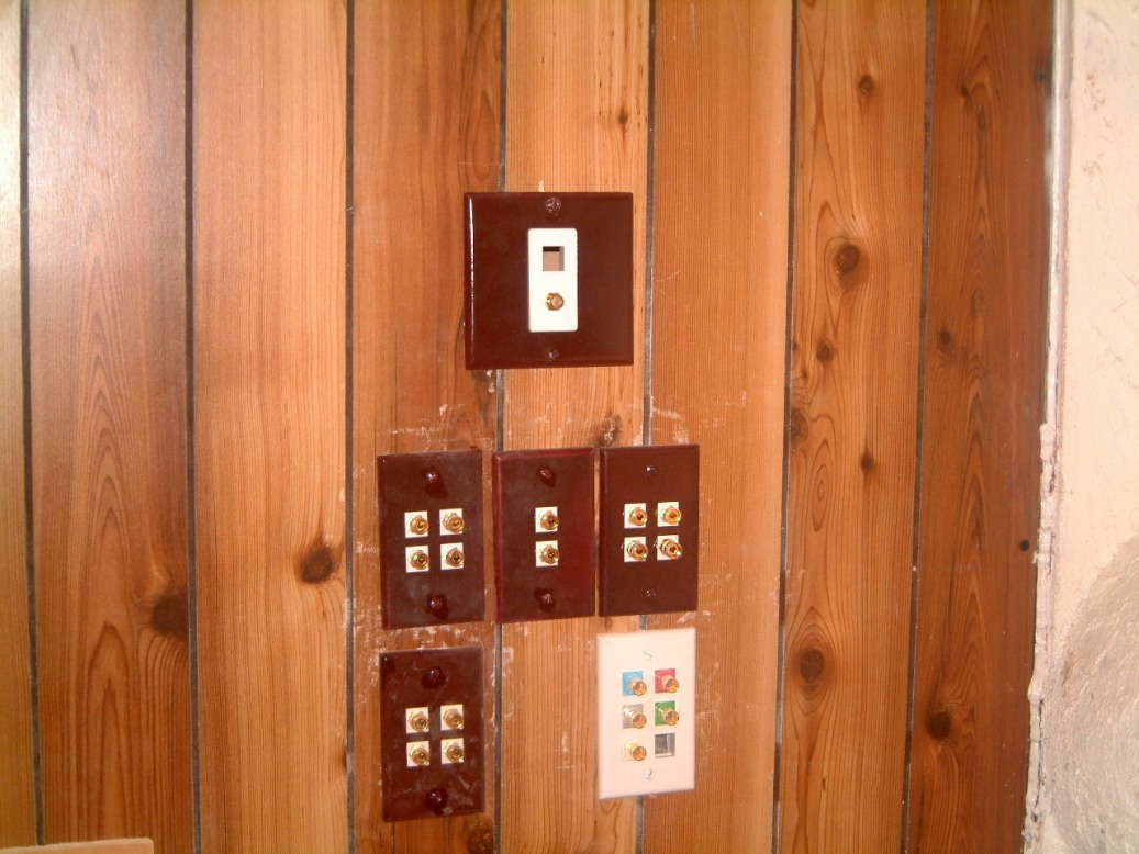
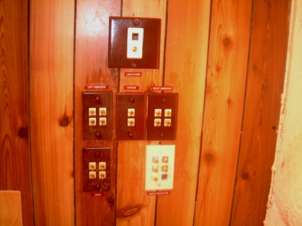
Then I will use foam to seal the compartments. The underside of the platform will be braced with 1" x 3" battens screwed and glued in place. I will fill the sub-woofer cabinets with fibreglass batts.
The front and west end of the platform faces will be sealed to the carpet by the use of a brown silicone. As the lower edge is not obviously visible, the brown will blend in with the dark red of the carpet. It proved to be almost impossible to remove the carpeting at the rear of the room, so I left it in place. Note that the baseboard has not been replaced when the photograph was taken. The reason was that the top of the platform will be carpeted, with it being run down the face about four inches with the underside of the edge being stapled from underneath.
March 8th to 13th, 2005
The problem of sealing the two sub-woofer compartments to the slightly uneven frames that support the deck, was solved. I was faced with having to use a belt-sander to even-off the irregularities so that the top could seal. However, on Sunday I remembered that I still had several rolled of closed-cell Neoprene, closed-cell Hypalon, that was specked-out to resist compression-set. The durometer was a bit high to use for fabricating skin diving suits. But it was ideal for sealing the sub-woofer compartments!
April 11th, 2005
I used a coarse open mesh carbide paper to sand-down the high spots and where the Locktite 'nail substitue' was used as a 'filler'. A long trammel showed-up all the small gaps that had to be sealed. I cut the closed-cell materal into strips of the required width, and used a water-based contact-cement to glue it down to all of the surfaces. The top of the platform was screwed down and sealed in place by the use of #10 x 1 5/8th drywall screws spaced on about 7" centers.
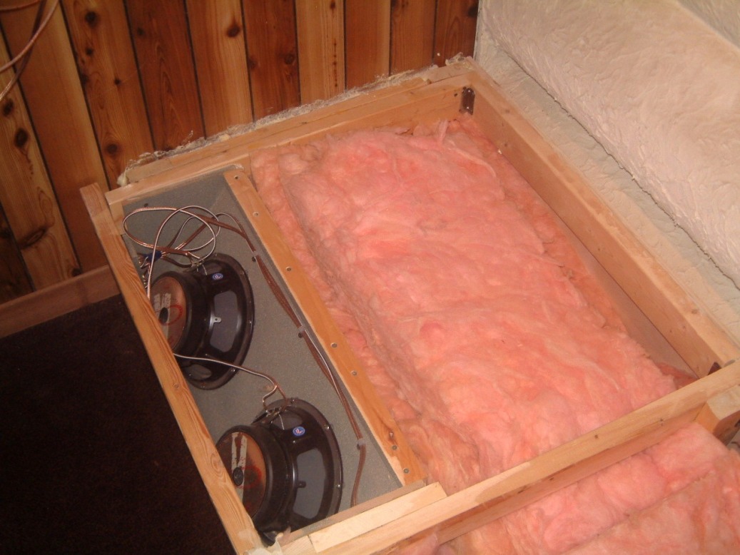

.
Here is the east end of the platform woth the fiberglass in place. The other
shot shows the blue surpaced closed cell foam in pace (but not glued down).
April 26th, 2005
The platform progresses. The top was finally screwed down with over 140 drywall screws from 1 5/8th" to 2 3/4" in length. At the rear of the platform I placed a chair guard. This was screwed to the 1/2" thick plaster coated large diameter tubing sections that form the rear wall of the media room. The left shot is of this rail. The center shot is of the eastern end of the platform with the wide corner cedar baseboard screwed in position showing the wooden buttons that hide the drywall screws.
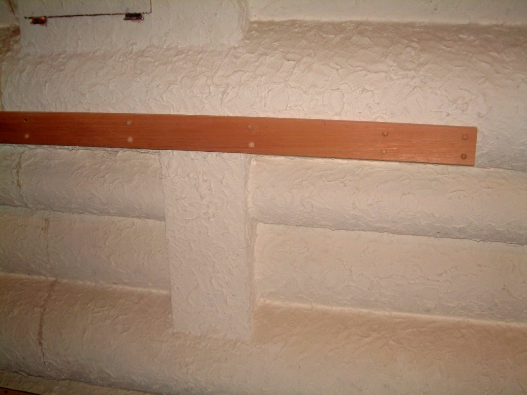

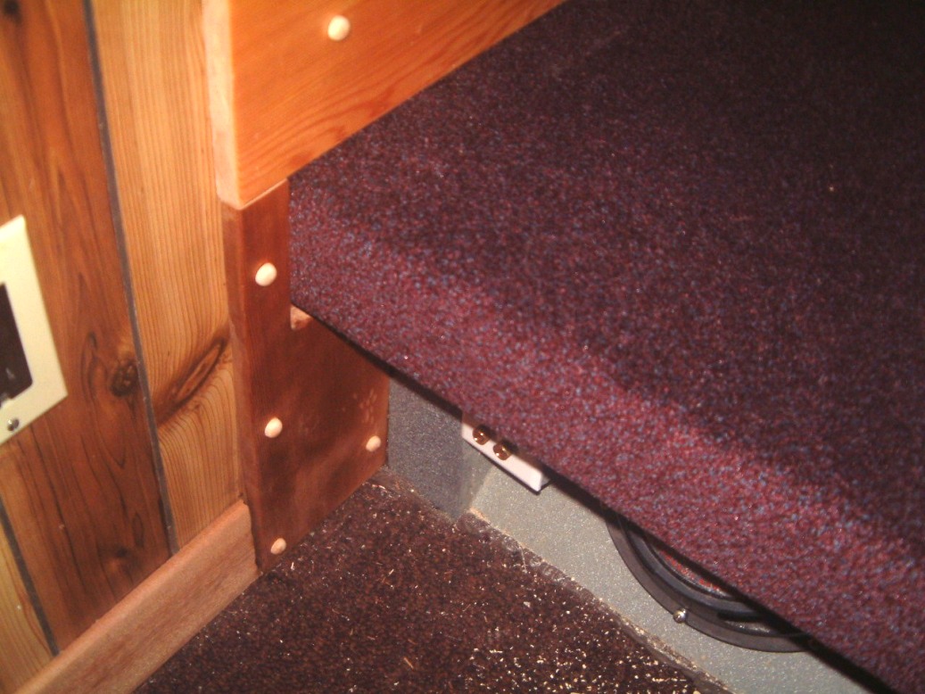
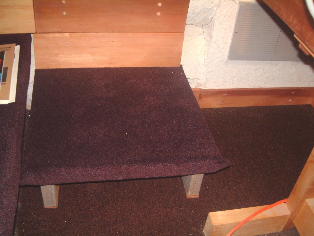

Rolling over the carpet at the front was a bit of a task until I realized that I could use a bunch of clamps to hold the front ends in place while I used ceiling tile staples to hold the carpet and staple it under the overhanging front. The next step is to construct a step at the western end of the sub-woofer platform. The way that it was planned, was to cut a 21" x 21" piece of 11/6" birch plywood and glue on four pieces of 1"x2" underneath. One traverse piece is spaced about an inch inward from the rear of the step and this allowes a piece of 1" x 6" cedar to be used as 'baseboard' at the rear. Because, I can use six countersunk holes across the rear of the baseboard to clamp the carpeting down, it makes it easy to use a latex-based contact cement to glue it in place. By rolling over the front edge of the step, I can use staples under the 1" x 2" to hold it up (down). Then, I'll use a 5/16" forsner bit to allow me to first use a drywall screw to hold the cedar baseboard flat against the wall, and then plug the holes with buttons. I can use a series of cup-washers to hold the outer edges of the carpeting. After that, I will use 1" x 4" cedar baseboards on all the perimeter walls.
May 4th, 2005
I realised that the old baseboard dated from 1981 - 82. Because the luan mahogany had started to split (we had a major leak in the plant roof in 2000 where the carpeting in the media room was soaked), the split areas started to buzz; it was time that it had to be redone. As an afterthought, I took some older chairs from the storage in the rear of our plant, and moved them onto the platform at the rear of our 'media room'. This is what they look like.
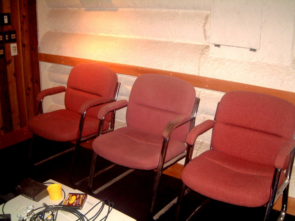
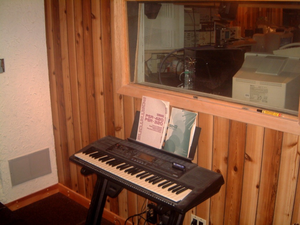
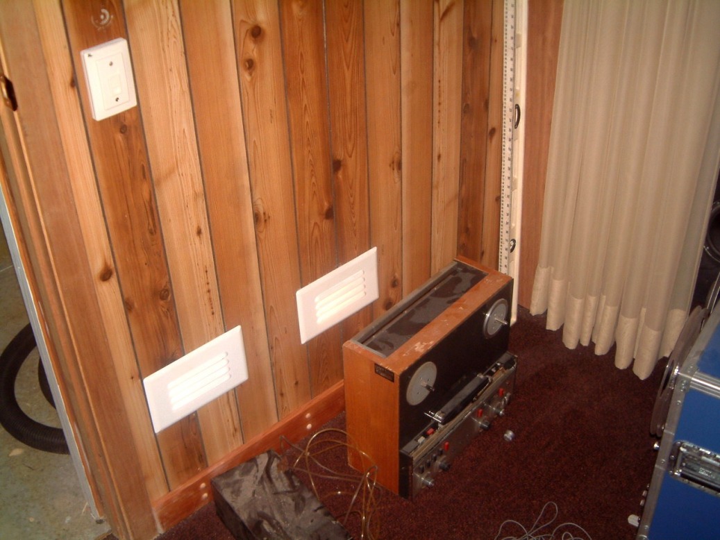
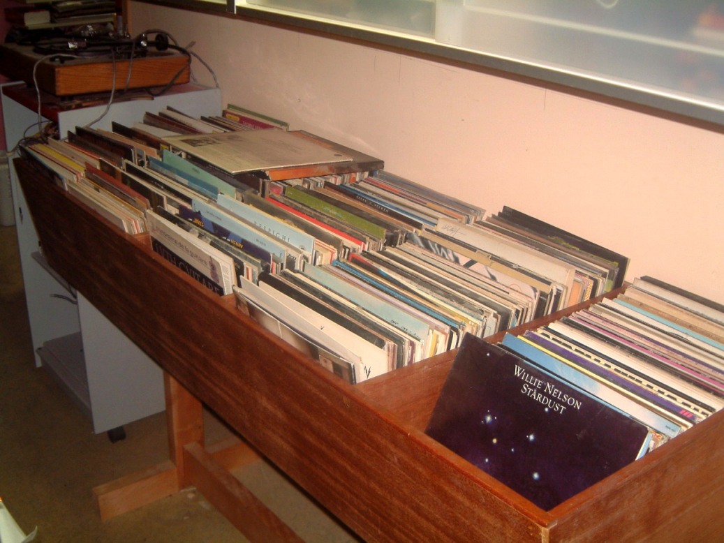
Note the color is different on the three chairs. We bought them in 1986 when my predecessor was the CEO of D. W. Electrochemicals Ltd. He retained a furniture 'consultant'. The color was supposed to be identical, however, the four chairs were in different locations in two of the old offices, and it wasn't until he was no longer with the company and we'd moved, that we realised that they did-not match! Two of the chairs (not see here), were for the officers of the company, and were on swivels. These lasted six years before they broke. So much for the 'consultants'. By the way, in frustration, I welded on new bushings on one of these swivel chairs and am now seated in it as I am writing this.
I had been postponing moving the record storage 'bins'.As they were at the front (north) of the media room, I moved the two older sub-woofer cabinets out, took all the records out and moved the bin ouside the media room into the hallway. They are underneath the two Ikea cabinets where I store thw DVD's and CD's.
Now I could use a ladder to drill a hole up at a fourty-five degree angle to run a a pair of wires for the center speaker. These are now connected at the set of wall plates at the east end of the platform. With the bin out in the hall I can move the MIDI 'piano' to the north wall without it getting in the way of the electronic drum set. I had an aluminium plate ready for the 24 microphone connectors to be screwed to the west wall behind the inner door. This arrangement makes it easier to move microphones. I have three sets of Microphone connecion plates, which, if they are needed, I can place on the opposite (east) wall. I am still looking for some place where I can locate the single Philips stere recorder, three 4-channel Tascan units as well as the portable stereo Televox unit and two other units.
But, it sometimes seems that the trivial things can stop you in yout tracks. I have a couple of small color cameras that I want to mount in the 'media room' so that I can see whats going on there which is out of my line of sight though the window in the wall. As they are RF, on different frequencies there should not be a problem. But, they need power supplies to function. So, I drilled a 1 1/16 hole in the wall and used two busings (designed to prevent 3-10 plastic wire from getting cut in metal stud walls. Getting tham lined up is hell as these walls are insulated with fibreglass. Normally I use a piece of rigid metal conduit (sharpened at one end) to guide a low-voltage (power supply for the cameras) through the layers of plaster board. Not today; a warped stud was in the way. The alternat is a wire coat-hanger. But it seems, that the only ones at hand, are plastic! Not to fret, we have too many metal hangers at home. (We think, that when they're bunched together, they act like rabbits, and breed!).
I found a method of snakling the varuous speaker and other co-ax cords in place. I will cut an opening in the wall of the 'tank-room' and use a spring-loaded panel on the drywall on the wall of this room to cover-up the opening. Then, I'll paint it to match the color of the room's walls.
May 15th, 2005
Odd job time once more. I realised that I had moved the cabinet that held our telephone. So, I had to build a supporting angled-shelf, that I could screw onto the interior west wall of the room to support the telephone, next to the door. Big deal, it took me three hours of time (I did it over a couple of days in order for the glue to set. Now, I really appreciate having the tools that I had on hand. I drilled a couple of holes in the plywood and the drywall. Then I used a couple of drywall screws to mount the 'shelf' just where it was needed.
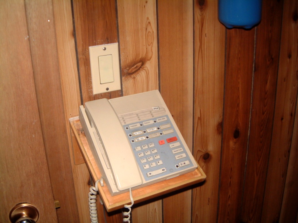 I placed it on the wall underneath the switch for the interior louver'd llghts.
These (four lights - two on either side of the room), are about six inches
above the baseboard; this type of illumination was used to prevent people from
stumbling over microphone cables.
I placed it on the wall underneath the switch for the interior louver'd llghts.
These (four lights - two on either side of the room), are about six inches
above the baseboard; this type of illumination was used to prevent people from
stumbling over microphone cables.
Next, I had to cut an opening in the wall of the 'tank room'. This is adjacent to the east wall of the 'media room'. In the photo, I had disconnected the temporary wiring as I wished to cut the various sets of wires to an appropriate length and form a solid solder connedtion where each wire had tp be clamped to thr rear of its terminal plate. I had to admit that using a 'fish wire' through fibreglass is allmost impossible! However, with the opening in the 'tank room' drywall, it seemed simple. I pre-cut a piece of 5/18 drywall to fit the opening and will use thin strips of spare 3/32 aircraft plywood to back-up the seams.
 I used a Canadian Tire Mastercraft Maximun Tool plunge saw, were the spiral bit
can preset to cut through only the thickness of the drywall without nicking any
wiring. One of the problems was just how to use a 1 3/4" hole saw on a
long extension (about 18" long). You see, it had to first make a
hole in the double plate, then, approximately 7" below that , there was
another double plate. All might have nails that the saw had to cope with
without getting hung up. The Cat 5e connector would fit through a 1 3/4"
hole with a bit of room to spare.. It would leave enough clearance for a co-ax
TV cable.
I used a Canadian Tire Mastercraft Maximun Tool plunge saw, were the spiral bit
can preset to cut through only the thickness of the drywall without nicking any
wiring. One of the problems was just how to use a 1 3/4" hole saw on a
long extension (about 18" long). You see, it had to first make a
hole in the double plate, then, approximately 7" below that , there was
another double plate. All might have nails that the saw had to cope with
without getting hung up. The Cat 5e connector would fit through a 1 3/4"
hole with a bit of room to spare.. It would leave enough clearance for a co-ax
TV cable.
June 2nd, 2005
Another delay. I had a older computer with the Windows XP Pro installed that never seemed to function the way it was designed. A solution seemed to be obvious. I made sure that Norton was current. (Remember that we only have a dial-up connection until we can get DSL. Therefore, I first managed to install Belarc Advisor by installing a Netscape 8 browser and configuring it, for now, for our current ISP without installing the e-mail. I first found out that it was running XP Version one and had Direct X seven and the older Media Player. Therefore I upgraded to Vesion two. I first had to install the automatic program as I had no desire to wait for several more hours! Having to use the dial-up connection to first remove the unneeded version one took about fifteen minutes. But getting the 108 Meg download took several more hours before the installation process could begin. Belarc Advisor scanned my computer for security flaws. It found that there were still 16 holes in my system. The scan itself took almost 80 minutes to complete. I had to shut down my computer to allow the updates to install.
June 4th, 2005
I purchased an inexpensive Laser Level and tried it out; but the tripod that came was too short to be used.
 As you can see, even by standing on the platform at the back of the room. the
beam is far too low. But, although I have several Manifrotto tripods, none of
them have the male screw to allow the device to be used. Well, I'll just have
to make one on the lathe.
As you can see, even by standing on the platform at the back of the room. the
beam is far too low. But, although I have several Manifrotto tripods, none of
them have the male screw to allow the device to be used. Well, I'll just have
to make one on the lathe.
June 15th, 2005
Yet another problem where we have the Flight Simulator set up. The series of phone extensions I had to use so that I could update the firewall and virus protection was a literal drag; we were afraid that sumeone would trip and screw up an important flight. So, before that probable event, I took the time to install a telephone jack on one to the steel columns supprting the roof of our plant.
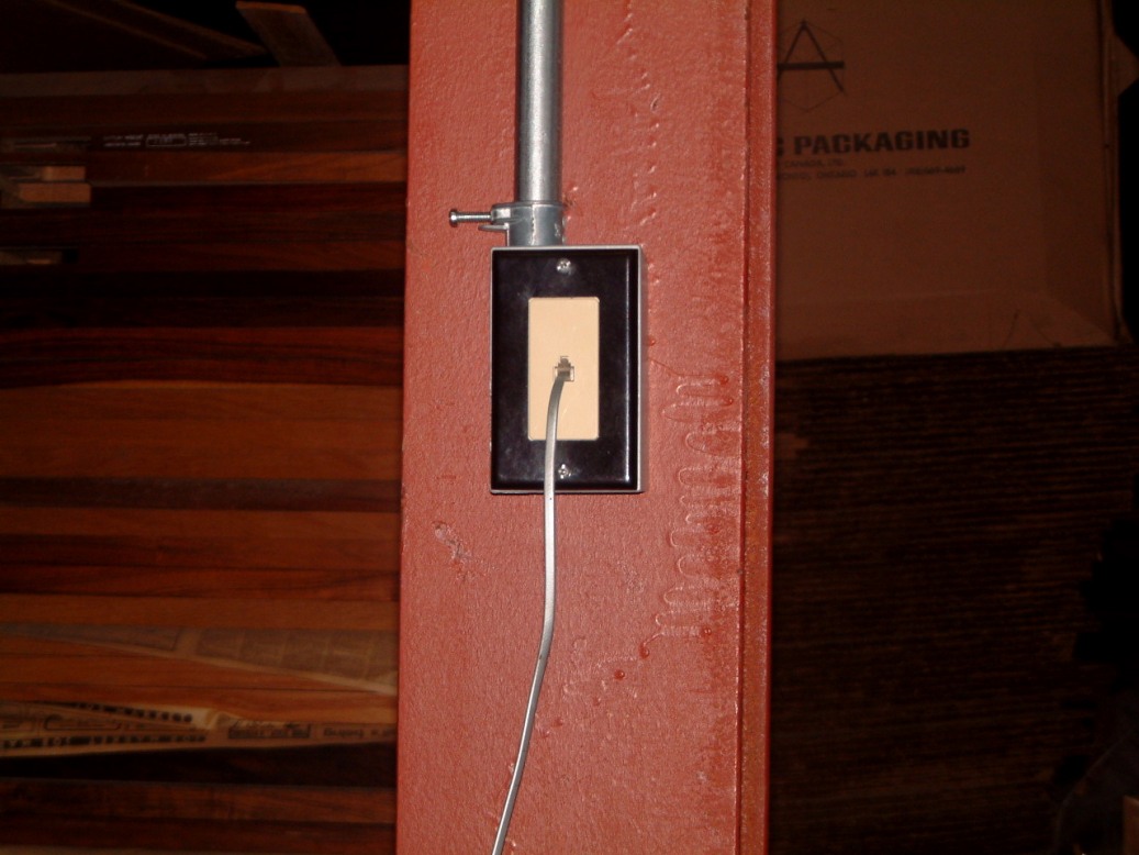 I have to comfess that I have had all the needed parts for about two years but
didn't have the free time to install them. I had to admit I estimated
that this job would take over seven hours to do. The only simple way, was to
use the steel pipe we employed to support the mixing-room stainless-steel lab
sink waste PVC water pipe' We had used perforated hangers every three
feet. We were able to use wire ties to secure the telephone wire. The
black PVC pipe rums overhead through the men's bathroom where it connects to
the vent and waste pipe for the drinking fountain. We had to install a 20
gallon tank with a submersible pump to use with the lab sink and eye-wash
'fountain'. Inside the hinge-side of the door there was just enough room
to mount a telephone line junction box, where I can drop several lines as I
need two, one for the postage meter modem, and another to connect to a pentium
two based computer where we store a spare customer data base.
I have to comfess that I have had all the needed parts for about two years but
didn't have the free time to install them. I had to admit I estimated
that this job would take over seven hours to do. The only simple way, was to
use the steel pipe we employed to support the mixing-room stainless-steel lab
sink waste PVC water pipe' We had used perforated hangers every three
feet. We were able to use wire ties to secure the telephone wire. The
black PVC pipe rums overhead through the men's bathroom where it connects to
the vent and waste pipe for the drinking fountain. We had to install a 20
gallon tank with a submersible pump to use with the lab sink and eye-wash
'fountain'. Inside the hinge-side of the door there was just enough room
to mount a telephone line junction box, where I can drop several lines as I
need two, one for the postage meter modem, and another to connect to a pentium
two based computer where we store a spare customer data base.
July 17th, 2005
After attempting to cope with almost a month of 95 degree F weather and almost 23 days of pollution warnings, I had to give up working in the rear of the plant. With the loading dock pull-up door open half-way so that we could load nearly a three-quarters of a ton of steel dies into a truck. Accompanied by some perforated metal alectrode clanks, not to mention a set of center tweeter mounted Rosewood Trimmed XG-10's (with a set of heavy (50 pound 300 to 1 C-core transformers accompanied by a pair of lighter C-core error correcting transformers), to be taken to a R?D place where further work can take place, I was pooped beond reason!
In tbe meantime, I had to pick op a pair of large daphragm condenser microphones. I had two pair of B?O ribbon microphones from the time that Bob Tucker an I first started to import them (circa 1956-7). That was about the time that we got involved with Dave Halfler of Dynaco fame. I remember that his sheet metal contractor reversed the folds so that we had to make a new set of power amlifiers for the New York High Fidelity Show.
Somewhere, I lent a pair of my personal ribbon units to someone in Boston, and had another pair 'liberated' from The Dayton Wright Ltd., plant about 1995-97. When we imported them these units retailed for about $120 each. Now Royer Labs sells a redesigned version for $1,100 US.
As I said, I am going to install a vertcal double row of 34 XLR connectors beside the inner door to the 'media room'. I will have to make the mike extensions long enough to be connnected to a 32 input mixer. However, I still have to connect to several four channel tape decks plus three stereo decks (one of which is a portable Stellavox). I have a two-row patch panel and enough Neutrik patch cords to serve for now. I remember Les Paul's technician (a relative of Mary's) and the amount of work he had to accomplish to get Les's Remix console running. I was able to supply some of the PC boards that were needed from our own stock. (At one time we had manufactured several short runs of mixers).
So I have unpacking 25 and 50 foot XLR extensions cables and attempting to store these things in an antichamber off the front-right side of the 'media room'. The mike stands will be stored in the 'tank room' for now (where I have stored some prototype cone speakers. At last count I still have several short-boom stands as well as several assorted single stands. I have a pair of calibrated Bruel ? Kjaer condenser mikes with their power supplies and heaters. I will use a double XLR connector plate beside the right-front side near to where I used to place speakers for phase, frequency and periodicity testing. These female XLR connectors wil only be connected to an older HP computer with a wide band analyzer, and pulse generator.
However, once more, the torrid heat stopped my work at 1:30 PM.
July 22nd, 2005
The XLR connector mounting plate for the west wall of the 'media room' posed a bit of a problem. The aluminum stock I had on hand, was from a old 'kick plate' that I still had in stock. It had taken a bit of beating since I bought it. It was warped, and 'dinged', but was still useable. Two hours under an oscillatig sander', after cleaning it up, I used a metal punch to make a twin row of 15/16" holes for the XL connectors, then drilled two diagonal holes to secure the connecerors, again polished the surface of the aumimum . I cleaned the surface. sprayed with a metal primer and follwed up the next morning, with a coat of 'dark grey hammertone finish'.
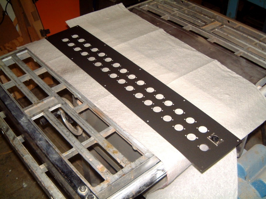
The next job is to make a pair of double light fixtures that I can use adjacent to both entrance doors to the 'media room'. I can make them from a couple of 15" x 7" 'handy-boxes,. these have screw-on covers and I'll cut two pieces of plastic with a divider half way along these boxes with the left end 'yellow' for 'stand-bye' and the right end 'red' for 'recording'. I have some 12 volt fixtures that I can use over each door and control both sets of lights from a three-way switch beside the mixers.
. September 12th, 2005
For over a monty, I have been busy at home attempting to do some urgent repairs. This in the mornings ( 7:00 AM) the weather has been OK (with the exception of a torrential rain that flooded many basements), however for last three weeks I was able to go outside for three or four days a week. In the '86's to the 89's's, we usually had a day and a half free, and it was rare that we had to spend 54 hours a week working at our plant.
However, things began to change after The 1988 when The Dayton Wright Group Ltd., ceased operations. We had to move D. W. Electrochemicals Ltd., norhward from Highway 7 and Leslie, to 3-97 nNewkirk Road North in Richmond Hill. Ontario.
As you can appreciate, we did not have the 'stock and tooling' sorted out so that a reasomable inventory could be run until 1998. So that we could not get a cogent web-site operational before 2001.
I have another problem; lack of time. Whereas, both hardware parts and electronic parts were easy to locate (locally) now an increasing number of items have to come from a central warehouse. And, it's not that some parts are not available, as the problem of having to select the exact part that is needed from a sometimes overwhelming amount of 'almost compatable' selection. A simple example is the incompatibly of 'support chip-sets' .When I was head of the R?D section for a firm in Boston, either I could generally locate a war-surplus part that could be modified to get a 'working prototype' up and operating OK in a reasonable number of hours.
Now, unless you have access to a carpenty shop, a machine shop, a plastic's and rubber molding faciliy, not to mention a complete electronics test facility....ect,.it takes a hell of amount of time to even to get a short manufacturing operation operating.
I suppose that is my 'Rant-of-the-Month'.
October 20th, 2005
Another major move in our plant caused an unexpected serious problem. I had to move a computer, an older Canon 8BPiiR lazer printer that was linked to a special board that allowed four times the normal resoution for printng. It used Ventura Publisher 2 which used the GEM system from Hewlett Packard. When a llong fiber lazer paper was used the quality of printing was exceptional. It took me nine months of use until I felt competent in its use To place it in thr proper perspective, we began its use in April 1987 to produce custom MSDS's for the Stabilant's. When we proposed a move north from our Leslie Street address, I had to gut the old offices on Newkirk and build a totally new table-bench arrangment. I installed a UL certified door and steel frame to meet the Fire Code Specks.
I had to ensure that the AC power would be sufficient to operate all the computers. At our Leslie address, low voltage was a major problem, in 1887 battery powered back-ups for AC operation cost about $600 each for a 250-300 watt unit, you were lucky if the power would last 15 minutes.\
At the Leslie address, the tenants overhead were computer programmers ane every time our power failed we could hear tge cursing from overhead. We had to contract with a phone answering service because our power went out daily at unexpected times.
So, you must appreciate why we have UPS Backup's on all our computers (including the postal meter).
When we moved the stuff from the front office to further back in the plant, I was not suprised when it didn't operate properly. Even with a 1,200 watt UPS, it was very dicey and the alarm on the UPS would sound after ten minutes. We had to use one or the overhead cab-tire drops that were rated at twenty five Amps to make the stuff reliable.
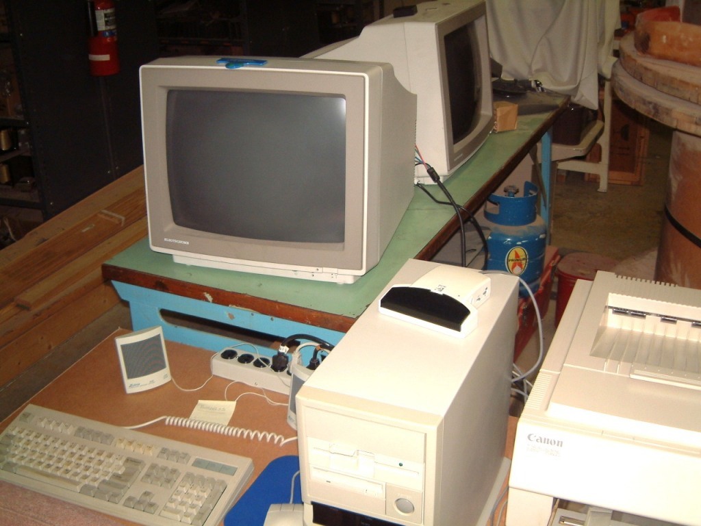
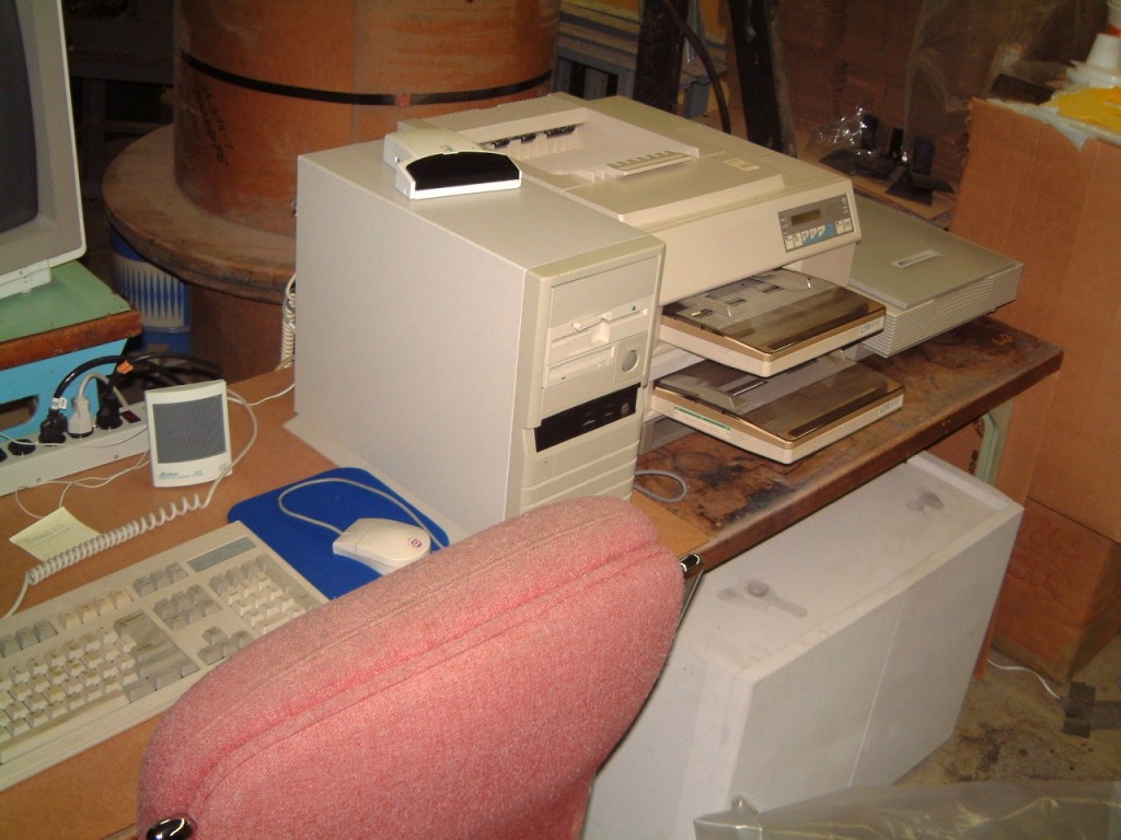 The
'drop' worked perfectly. But it was about two weeks later that I found out from
other buisness in the area, that unnexpected brown-outs had been occouring for
several weeks!
The
'drop' worked perfectly. But it was about two weeks later that I found out from
other buisness in the area, that unnexpected brown-outs had been occouring for
several weeks!
December 14th, 2005
After too long a hiatus (Caused by a major spam overload coupled with a barrage of worms and spy-bots that was driving everyone on the internet nuts that was traced to a copy protection program where a hacker was able to locate the vunerable ports and exploit them to disrupt normal use if the internet by causing a denial-of-servive attack - how many times has your service failed or been disconnected). Far too often this has become the usual sort of thing - it has spread worldwide over about a two month period..
My ISP'sserver has failed innumerable times which is why this web-site is so far behind.
January 30th, 2006
A unexpected respite as all the MSDS's have been updated as at January 3rd, 2006i As Stabilant is marketed in many countries, we have to make them available in French, Italian, German, Portugese and Spanish. Now, it has been done, I have begun convering my monitors to comply with RoHS regulations which probit the (thick lead-based crystal glass) employed in monitor screens. Thank heavens that the price of fast-refresh screens has dropped dramatically in fifteen months. We began the converion in some of the monotors in our plant. As exoected, two od the computer desks required alyeratioms so that the monitors would not slide off the inclined 'shelf' that was designed for the deeper and heavier CRT types.
That was not a problem for the multiple computer multiple monitor flight simulator. I began by replacing the 'server' computer monitor with a very fast response nineteen inch flat monitor made by Acer. I had a problem which I thought was caused by the VGA connector; but it proved to be the AC connector had not been plugged in all-the-way.
 The clarity was startling until I realised that the olf twenty one inch monitor
was long past its prime. Even though it was about seven years old, it must have
seen extensive use before I bought it as a used unit. I have the four other
monitors that flank the centeral unit. Now I realise just how much that wide
cream-buff colored frames on the CRT units 'bugged' me. Now its worth while to
adjust all the units to mimimise or elimimate tjhe 'overlap', if I can.
The clarity was startling until I realised that the olf twenty one inch monitor
was long past its prime. Even though it was about seven years old, it must have
seen extensive use before I bought it as a used unit. I have the four other
monitors that flank the centeral unit. Now I realise just how much that wide
cream-buff colored frames on the CRT units 'bugged' me. Now its worth while to
adjust all the units to mimimise or elimimate tjhe 'overlap', if I can.
February 10th, 2006
Back to the Media room again; I have thought about something for several years and finally decided to do it. I have a hell of a lot of free space underneath the elevated access platform for the isolation chamber. The platform is about 48 inches above the concrete floor leaving about 41 inches clear. There is a water heater and pump at one end as the manditory safety shower is at the south east end of the elevated platform. We have a stainless steel lab sink in the area to the east. As there is no drain at the south end of our building, we had to pump the water up and over nortward to one of the drains. We had to install an eye flushing 'fountain' at the other end of the room and this too needed a drain.
So there was plenty or room to locate several power amplifiers under the platfom.
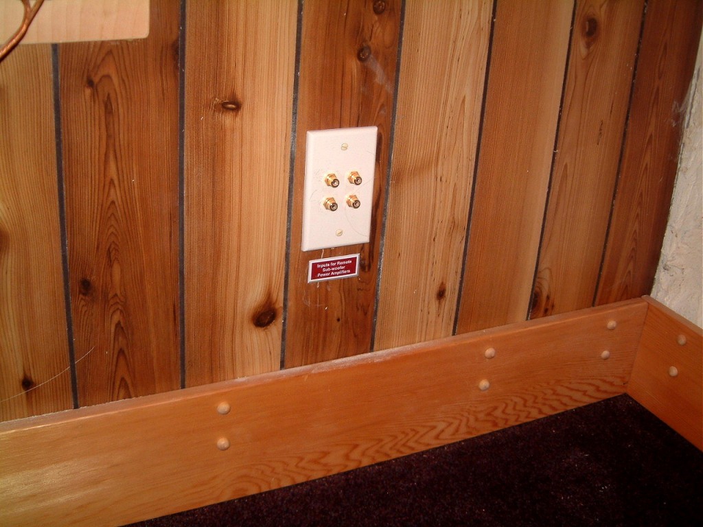

 Here are the three shots of the setup. The left one is the RCA type connectors
for the power amplifier inputs. The middle shot shows the output cable bushing
for the Sub-Woofer output cables. The right one is the ends of the cables. I
almost got stuck when my cell-phone belt-carrier snagged on the stair raisers.
It took me ten minutes to get free as I had no way of seeing what had snagged.
Believe me, concrete gets harder by the minute especially in a cramped area.
Here are the three shots of the setup. The left one is the RCA type connectors
for the power amplifier inputs. The middle shot shows the output cable bushing
for the Sub-Woofer output cables. The right one is the ends of the cables. I
almost got stuck when my cell-phone belt-carrier snagged on the stair raisers.
It took me ten minutes to get free as I had no way of seeing what had snagged.
Believe me, concrete gets harder by the minute especially in a cramped area.
But there is more work on the west side of the media room. I built a frame for the input (XLR) connectors and sprayed it with a gray hammertone finish to match the panel. I used a rotary bit tip cut the plywood and the Gyprock. It wasn't as messy as I hadimagined. With the hole open, now, I had to hold the thing in position. Several countersunk Gyprock screws were ideal. So I appllied waterproof glue to the back of the frame and screwed it to the wall.
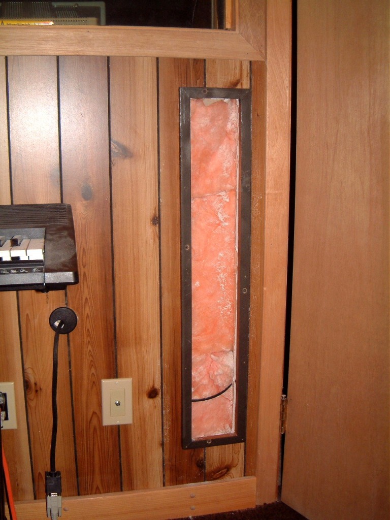 I was deligted at the ease wich it fit, and I resolved not to put things off as
much as I'd been doing for several months. I'd also reasoned-out a methof of
getting all the wiring into the assorted wall-mounted connectors on the east wall.
Reverting to the east wall, I finally was able to run all the assorted speaker,
Cat5e, and all the other wiring through the 'Tank Room' room wall. I was able
to use a thin spirol router blade to give me a 3/4 inch deep x 6 inch wide area
where I was able to place the wiring.
I was deligted at the ease wich it fit, and I resolved not to put things off as
much as I'd been doing for several months. I'd also reasoned-out a methof of
getting all the wiring into the assorted wall-mounted connectors on the east wall.
Reverting to the east wall, I finally was able to run all the assorted speaker,
Cat5e, and all the other wiring through the 'Tank Room' room wall. I was able
to use a thin spirol router blade to give me a 3/4 inch deep x 6 inch wide area
where I was able to place the wiring.
 The photo shows the
clearance cuts in the supporting structure that was needed to make clearance
for the wiring. Fortunately, these were 2x ?? (double thickness) plus 5/8
plywood for the horizontal beams.
The photo shows the
clearance cuts in the supporting structure that was needed to make clearance
for the wiring. Fortunately, these were 2x ?? (double thickness) plus 5/8
plywood for the horizontal beams.
Februrary 25th, 2006
More unexpected tasks; the modem on the Win XP Pro pooped out, becoming 'click infested' and could not connect. I had changed to a 19" flat screen monitor two days ago so it was easy enough to replace the modem. The previous 21" monitor was a back breaker as it was 'overly robust'.
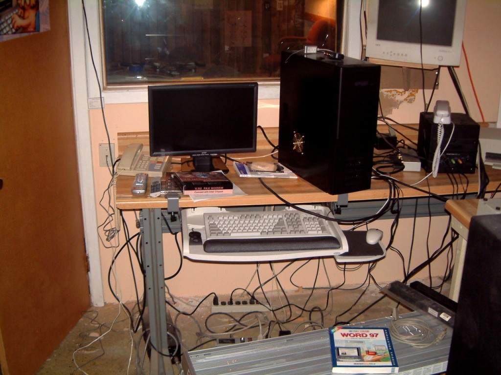
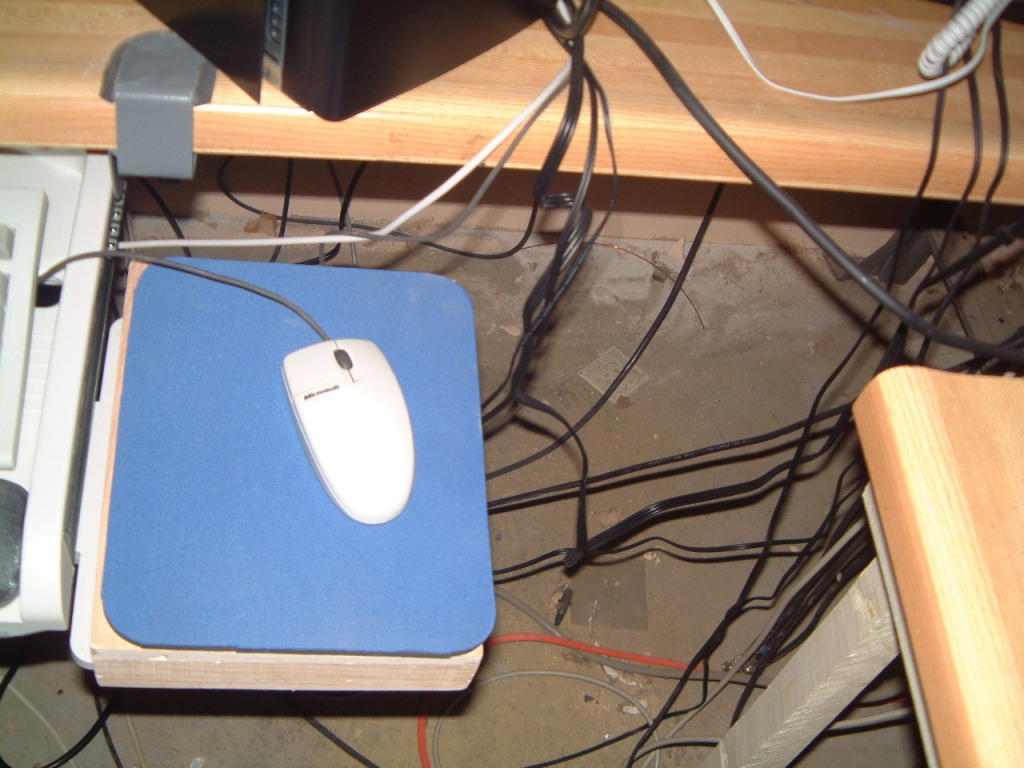 As I had been working 'till 2 AM the night beore, I did not expect this! Note
the Word 97 manual. It went missing sometime in 2000; and it took a
crisis to locate it. It fell off the south end of the table where it lay
undesturbed.
As I had been working 'till 2 AM the night beore, I did not expect this! Note
the Word 97 manual. It went missing sometime in 2000; and it took a
crisis to locate it. It fell off the south end of the table where it lay
undesturbed.
March 5th, 2006
I beleive that I cannot delay moving the audio and it's subwoofer to a low shelf under the east table that faces the media room thro' a double window. Because of the accumulation of dust, i did not want to do it. The Epson 400 printer was failing and because it was at the south end of the table, it was almost impossible to add paper or replace ink cartriges. So I built a low platforrn that would fit at the southern end.
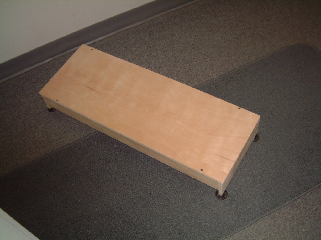
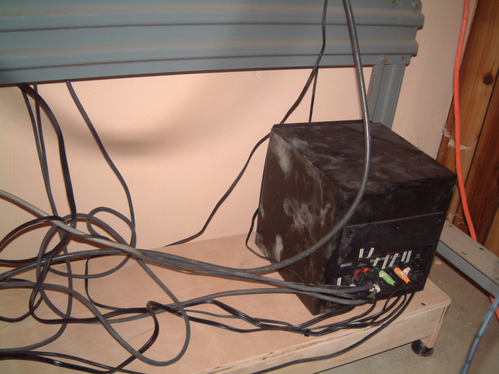 The sub-woofer shows the dust on the floor as well as the wiring that has yet
to be organized. I will need to use plastic clips under the bench to sort out
the wiring.
The sub-woofer shows the dust on the floor as well as the wiring that has yet
to be organized. I will need to use plastic clips under the bench to sort out
the wiring.
March 8th, 2006
Progress is slow, I had to conceal the wiring from the rear ceiling-mounted sorround-sound speakers. I had run the wiring above the hung ceiling., but at the last edge, the wiring was hanging down. I used a plastic molding running down the wall to hide the vertical wiring. Alas, the drape on the wiring pulled it free. I realised that I could use folded over vinyl tape and a staple to ecure it at the top ends of the plastic covers. I located a doubled male to male RCA type adaptor and was able to use this to add a five foot extention to both sets of wires.
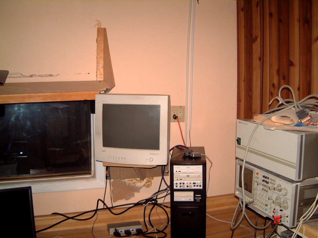
Now I was able to move the printer/scanner to the right (the south east end) of the bench.
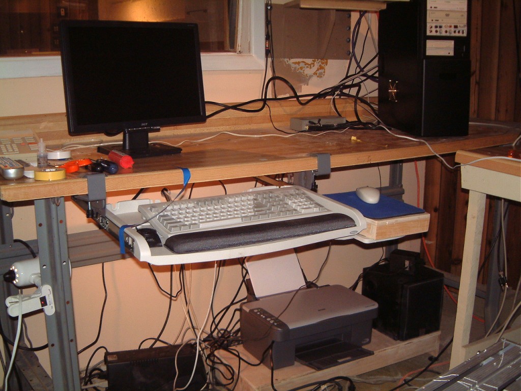 At long last, I had enough space so I could move the mixer onto the bench. But,
I had to wait for the delivery of the swivel mounting of the ninteen inch
LCD monitor. For now, it is mounted on Acer's stand. As you can see from the
snap, the keyboard and elevated mouse pad are able to slide back under the
bench-top.
At long last, I had enough space so I could move the mixer onto the bench. But,
I had to wait for the delivery of the swivel mounting of the ninteen inch
LCD monitor. For now, it is mounted on Acer's stand. As you can see from the
snap, the keyboard and elevated mouse pad are able to slide back under the
bench-top.
March 22th, 2006
It's time to get rid of all of my CRT type monitors. Under RoHS legislation these cannot be sold after June 30th 2006. Before the deadline, they can be disposed of as hazardous waste. After that municipalties are free to charge a fee for disposal. Rembenber that these monitors use strong glass that ii very high in lead. Knowing how many States, Provinces, Cities are short of funds, I expect that any fees for disposal will not be reduced!
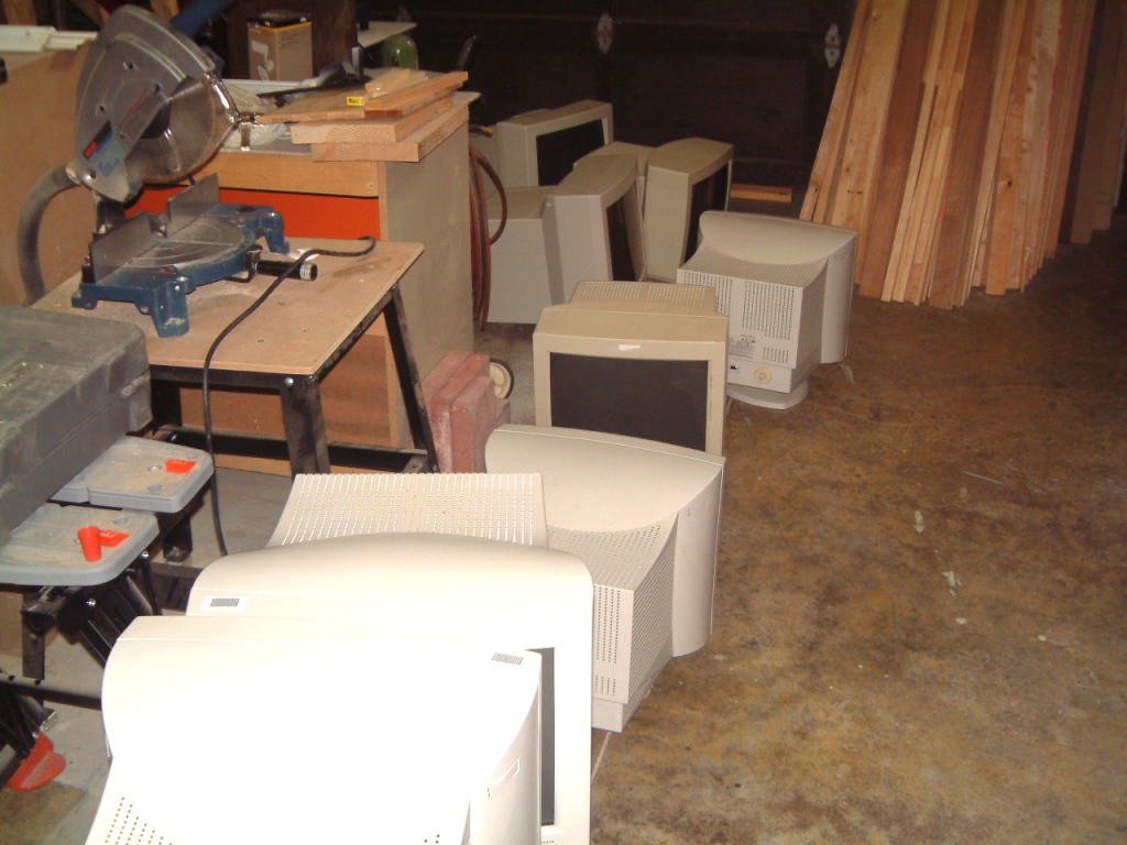 I never ever thought that these would be banned, no, I have to retract this.
Perhaps, it might have been intuition, but for the last four years I have only
purchased 'used' - 'off lease' monitors. These generally run $150 (C) for a
nineteen inch monitor; or cheaper if there is any sign of burn-in or reduced
brightness/contrast.
I never ever thought that these would be banned, no, I have to retract this.
Perhaps, it might have been intuition, but for the last four years I have only
purchased 'used' - 'off lease' monitors. These generally run $150 (C) for a
nineteen inch monitor; or cheaper if there is any sign of burn-in or reduced
brightness/contrast.
Well, buyer beware! I am still suprised that the RoHS regilations have never been mentioned by any Consumer's publication!
May 9th, 2006
The Canadian tax's completed, perhaps I may have time to add some things that I had to get done. The one item that's been bugging me is the instalation of a swing-away side support for the nineteen inch Acer monitor.

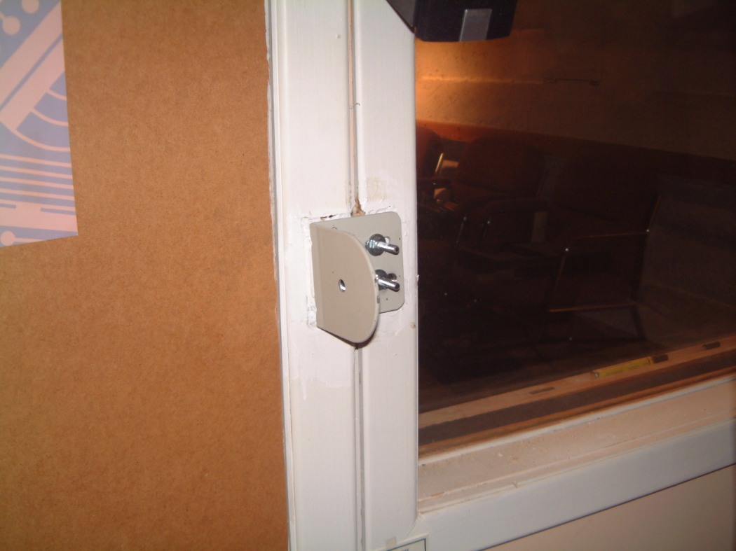
 The difficulty was that I had to place it at the side of the mediaroom window
half-way over the door-frame. Oh well, another breach in the sound insulation.
I was finally able to install a better indoor antennae up in the mezzanine area
above the media room. With a self-powered antennae cupled to a five way coax
amplifier now, without cable, I can watch TV.
The difficulty was that I had to place it at the side of the mediaroom window
half-way over the door-frame. Oh well, another breach in the sound insulation.
I was finally able to install a better indoor antennae up in the mezzanine area
above the media room. With a self-powered antennae cupled to a five way coax
amplifier now, without cable, I can watch TV.
The third photo shows the final mounting for the 19 inch monitor. (obviously the actual monitor isn't dhown as I am having problems locating the screws for the Acer unit. The mounting required too much time on the milling machine to position the slots for the flat-headed 1/4" x 20 x 2" machine screws. Part of each screw had to be cut off as thew were too long. I coulf not afford to allow the metal from the bolt shortening to scarmy plastic lens try-focals. My safety glasses are quite thick and I had a problem with blurred vision. But, the shortning went fine.
I am going to operate the media-room on a Win 2000 computer (with 7.1 speaker set up). For the time being, I'm using Win XP pro in the control room with a cable port in the wall to connect with the BARCO unit next door. I am connecting all of the speakers via a set of wall plates (still).inside the room itself.
I still have to hang several doors around the rear of our plant. Several years ago I was optimistic when I loaned a (was it Freud clamp-on hinge template for use with a small router. I haven't seen it since!
Perhaps by June, I will be ready to install a speaker level control unit tkat I can afford. The so-called preamps (non-gain voltage followere (ne mixers), run over $8,500 US up to $14,500 US.
May 18th, 2006
I neded four hands for the final installation of the swing-arm 19" Acer monitor. I finally had to resort to using one drop of Lock-Tites bearing mount cyanoacrilylic.
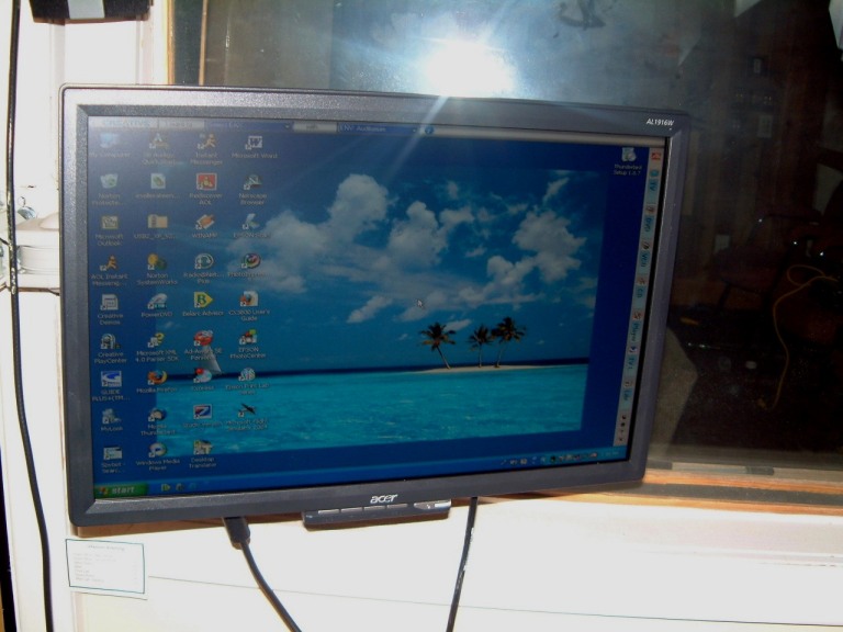

The left shot is the general appearance if the swing-arm mounting (the power and the monitor connection are still hanging down, these will be routed inside the swing-arm.
May 20th, 2006
At last, I have the Flight Simulator opereating with five Acer flat screen ninteen-inch monitors that have a response time of 8ms.

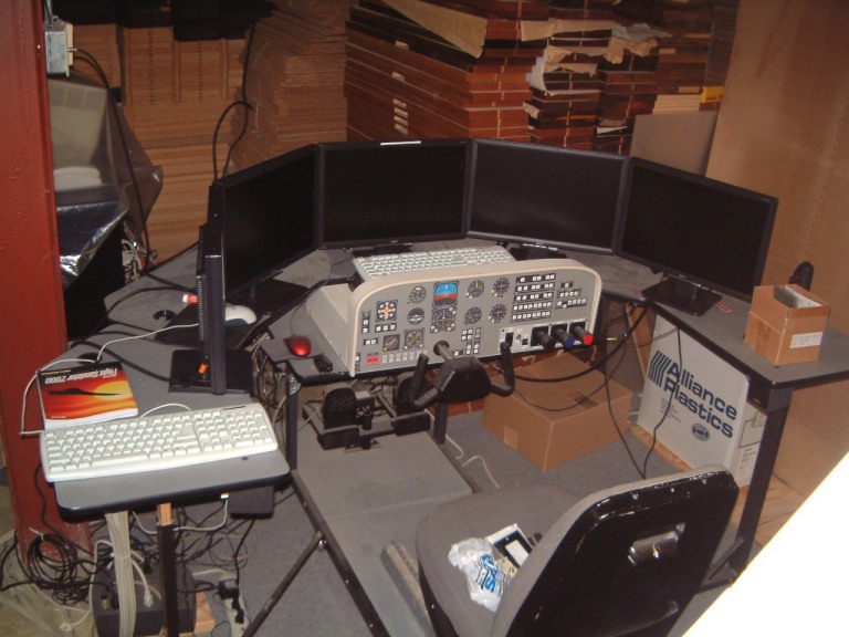 These seem to be
fast enough to handle the fastest manovering of a Cessna 182, I have not tried
it on a Lear Jet.
These seem to be
fast enough to handle the fastest manovering of a Cessna 182, I have not tried
it on a Lear Jet.
June 5th, 2006
More catch-up work. We have to install a back-up diesel powered three phase 230 volt 4.5 Kwatt power generation system for emergency use. Years ago in anticipation of a power outage, I purchased a distribution unit made by Gould Electric. However I never could make the time to locate the plastic power boxes for the installation.
Enough excuses. Here are the pictures of the needed box.
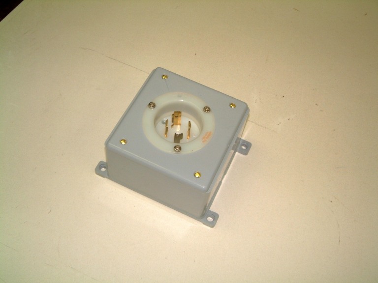
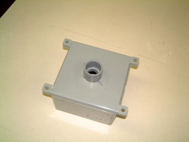 Appears simple enough, doesn't it? However, the orginal boxes were too small
for the connector to fit. At the time wider boxes were not readily available.
Five years later, I finally locaed a source.
Appears simple enough, doesn't it? However, the orginal boxes were too small
for the connector to fit. At the time wider boxes were not readily available.
Five years later, I finally locaed a source.
Next, I wanted a wall mounted industral grade switch for the double-bag dust disposal unit that I have had in the carpenter shop since 1978. This unit was too loud for comfortable use. So I decided to place this thing outside the carpenter shop and use a seven-inch hose through the partition. I found the switch I needed and mounted it un the inside wall of the carpenter shop.
 Now I can turn on the unit without having to open the door. I'll make a sound
reducing enclosure with a wide-enough door on the side and a sealed top, with a
nine-inch exhaust duct on the side so it can be exhausted out one of the
widows.
Now I can turn on the unit without having to open the door. I'll make a sound
reducing enclosure with a wide-enough door on the side and a sealed top, with a
nine-inch exhaust duct on the side so it can be exhausted out one of the
widows.
June 26th,2006
I received a shock after downloading a Quick Time *.tiff file. I had to reconnect twice to our ISP as on the first connection I received one of those horrible warnings, a red target with a superimposed yellow exclamation point. Our firewall disconnected my computer. I had to re-boot the computer to continue. I was able to download the 6 Mb file.
I used another program to reduce the file size by a factor of two so I could print it out. OK, job done. I had to alter the format to another *.img compatible with Ventura Publisher 2.6.
Three days later, I started to print some photos. One went though, then I received a paper-jam error. Strange, I'd been using fresh Kodak Glossy Photo paper and I had not jammed as I was half-way though a print. Nothing had fallen into the printer. I was able to form-feed the paper. So I rebooted the computer, cleared the monitoring and re-booted again. Same error signal. So, I removed the software. Ran a virus scan. OK. Re-istalled the program. Same result. 'paper jam. No paper had been put into the printer. Oh well, must be time to replace the printer. In case somebody smirks, Everything in our plant has a battery powered UPS back-up. I don't have any ground loops either. Each computer is seperate and several operate from isolation transformers.
I bought a new printer The system shut off when I plugged in the printer (nothing had been connected to the computer). So I rebooted it once more. Put the CD-rom into the drive and installed it (following the instructions to the letter). After three attempts, my computer would only run in 'safe mode'. Six years of work gone! Nothing I could do could reverse it. Was the Quick Time *.tiff file corrupted with a strange time dependent port-seeking worm? Our expert was able to use a bootlog file from a week earlier to get the combuter to operate. After a major cleaning I was able to do an update on a set of computer files for another web-site we operate.
Two more virus checks, AdAware + SpyBot S?D and the computer was operating about 1.3 times it's previous speed + the new .printer was great!
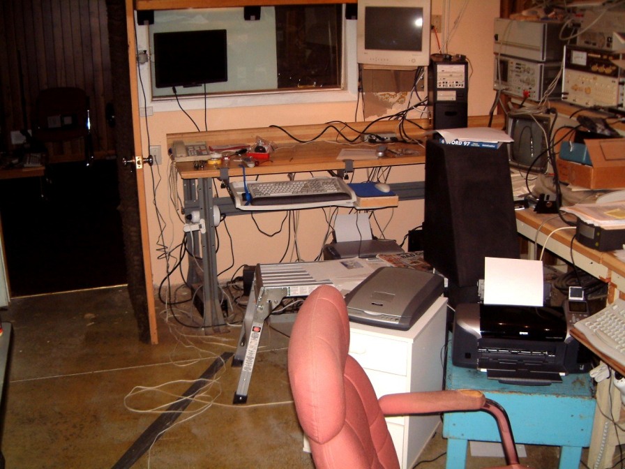 Visions of five years redoing work vanished!
July 11th, 2006
Rework again. The power backup box didn't fit as it needed a waterproof cover to pass electrical inspection - and I couldn't locate a simple cover that would work. So back over to Hill Supplies that is a couple of blocks north and a block west., They had a Hubbell snap down sealing cover that was ideal. Four proper drill size for self-tapping screws later I was in buisness.
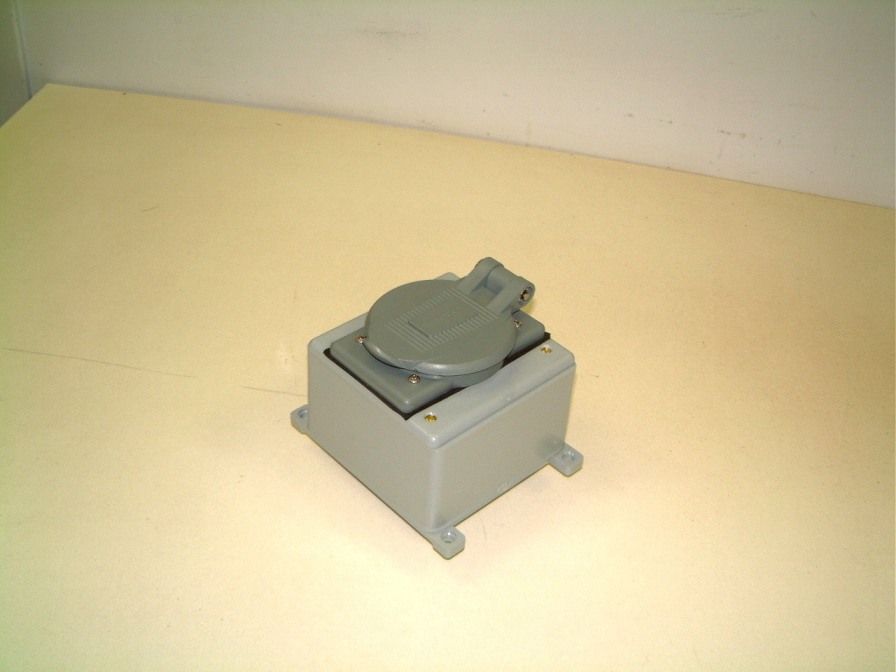
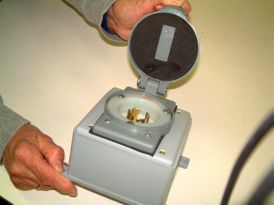 Well, it was worth it - a much neater and safer final result.
Now for the insallation, This involves a run of 3/4 inch plastic conduit mounted through thr rear brick wall. I have to drill a hole through the wooden inner wall, followed by a diamond hole tool through the external brick outer wall. Four Rawl Plig anchors will secure the buv in it's proper location. The clearance hole will be filled with fungud-proof silicone sealant. At the farr wall, the connection will use a ninety degree tube fitting and a coupling for another box that has a mating connrction on the top. Another horizontal tube will pass through the inner concrete wall.
August 15th, 2006
After two weeks of trying to get Microsoft's Digital Imaging Suite 2006 + Pinacle Studio v.10 working with my collection of S-VHS recordings that were made on a Panasonic (vintage 1991, then top of the line) I realised that the rear connection to my ATI card was loose. It took an hour to re-configure the card to work wth the S-VHS output from the player. A couple of tapes were playes to assess the quality of the tape. I wondered if I should dig out the Farouga line quadrupler to enhance the siglal or was it worth the effort? Laziness won out - experiment later.
A more pressing need was to construct a wheeled shelving unit to handle twenty-two vears accumulation of electrical stuff such as mamy Hubble Twist Lock connectors, a host of boxes, swithes, distribution panels etc., most all in the cartons or sorted out. We had been using an obsolete Leigh SPA Preamp burn-in rack . And as it was dounle sided, and was too heavy it took too much room. In a a rash moment I promised to construct a replacenement, Ten days later it was ready to sand and varnish. However it couln't be completed without sanding-down and varnishing.
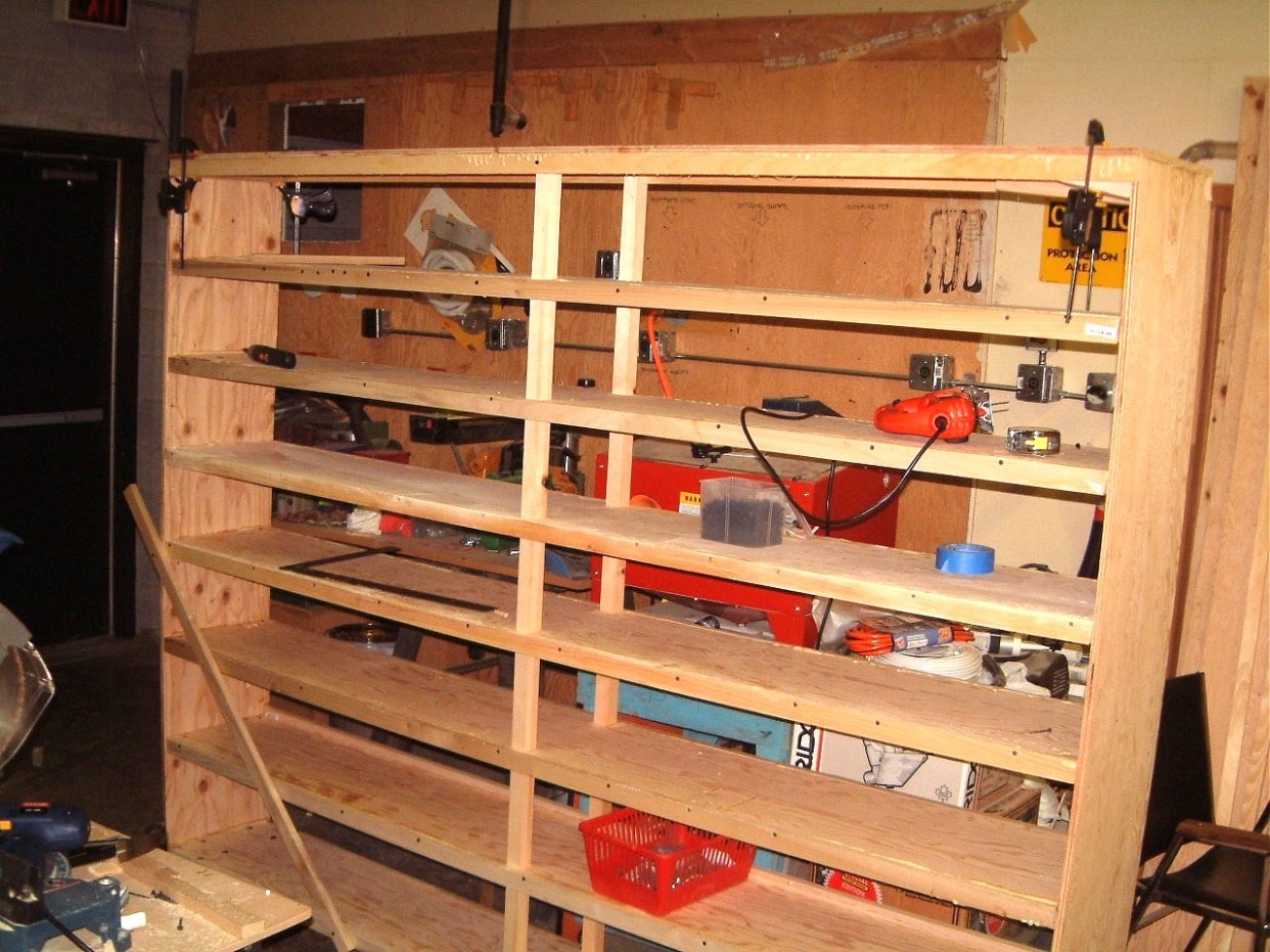 This is the
start. I plan to use strips of white pine to hide the edges of the edges of
11/32 inch G1S fir plywood.
This is the
start. I plan to use strips of white pine to hide the edges of the edges of
11/32 inch G1S fir plywood.
August, 25th, 2006
Time shure does fly: the shelving had to be delayed until I managed to set-up to tranfer fifteen years of s-video tapes to DVD's. Of course I had to get a 46 Mb Upgrade to Pinacle Studio v.10?.
I began with the current version starting with the first Microsoft 486 FS (slow), adding some scenery enhavcements. We used this at the first Comdex in Las Vegas, as a 'grabber'.
Since that first show, we upgraded the FS console to a five flat screen (all 19" screens). More later when I switched from the older Panasonic S-Video camera to the Sony HDR-FX1 HD camera and am able to master it.
Back to the shelving.
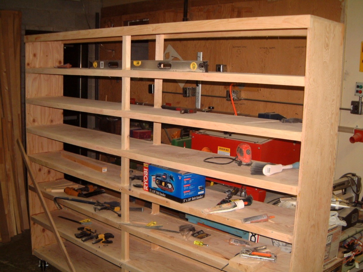 I forgot how much
filling and sanding was needed for a top grade set of shelves.
I forgot how much
filling and sanding was needed for a top grade set of shelves.
September 5th, 2006
I started (again) on the perpetual upgrade on the flight simulator. I am getting ready for DSL on the computer array. This involves adding a router - D-Link DI-604 unit with an input and four outputs one of which will be used to connect to the existing switch
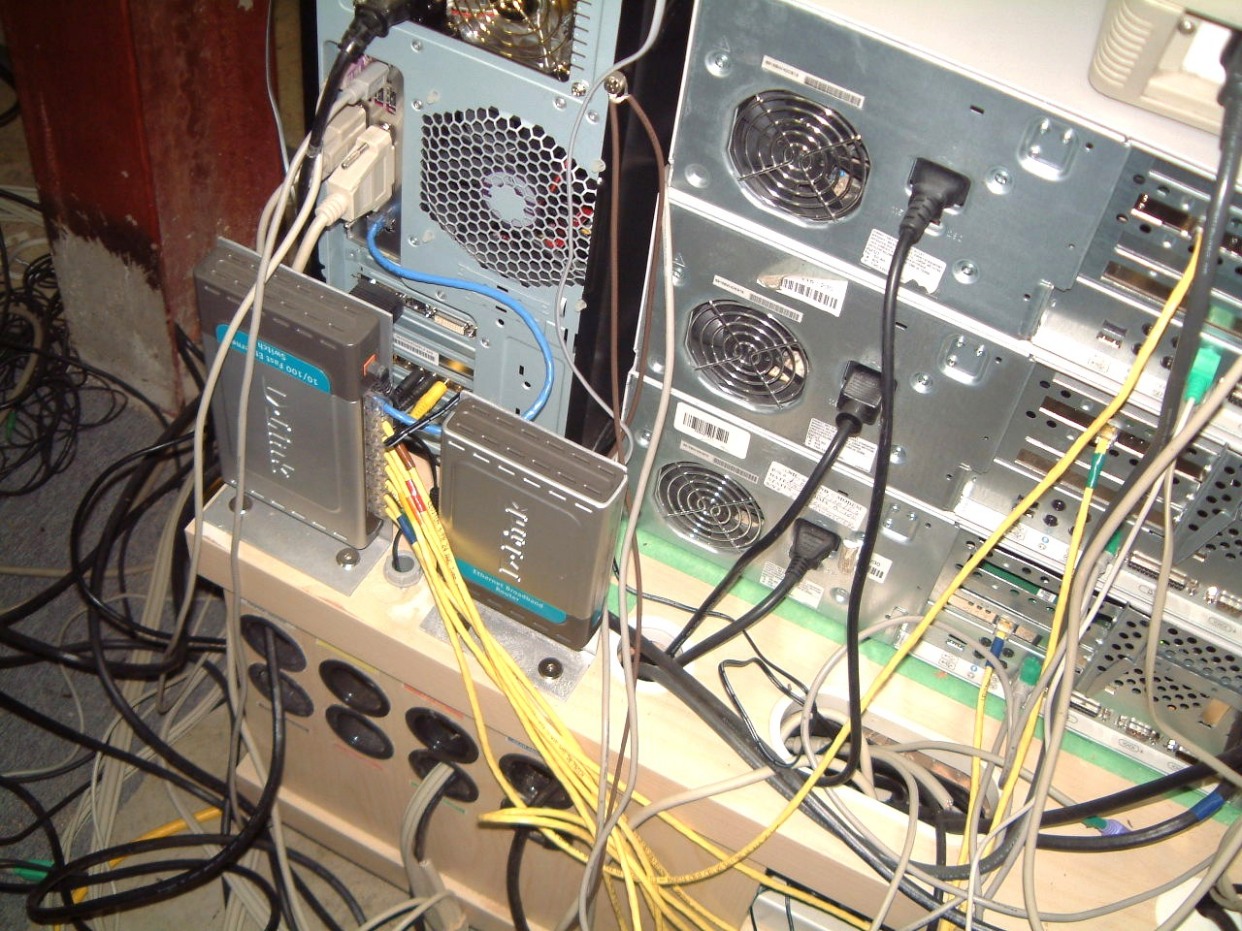
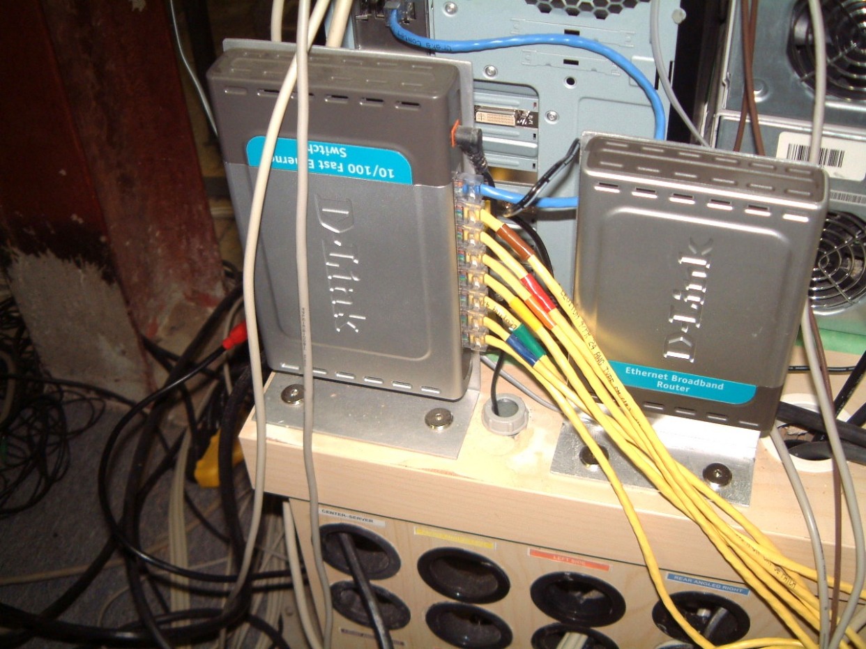 This involved adding another verital aluminum bracket to the rear of the
computer table. I followed the same proceure as the original mounting. I used
2" long flat (hex head) bolts with the same hex-head anchors (nuts)
underneath the two inch thick table. It uses resin impreg hexagonal cells to
reinforce the table with thicker material on the top and underside. Its light
(thank heavens its on six castors). I'm waiting for delivery of the new DSL
modem. More to come after I update the WidevieW software.
This involved adding another verital aluminum bracket to the rear of the
computer table. I followed the same proceure as the original mounting. I used
2" long flat (hex head) bolts with the same hex-head anchors (nuts)
underneath the two inch thick table. It uses resin impreg hexagonal cells to
reinforce the table with thicker material on the top and underside. Its light
(thank heavens its on six castors). I'm waiting for delivery of the new DSL
modem. More to come after I update the WidevieW software.
October 22nd, 2006
95 % of the Cat5e wiring is in place. We installed a wireless router and a wireless unit on a spare computer that runs Win 2000 One if my spare ATI All-in-wonder card ran without a problem. As I picked up three used IBM computers I believe that I can install two of them in the fight simulator running a higher capacity graphics card.
But after operating perfectly for two weeks, one of the IBM computer seemed to go wonky, now I cannot get into the safe mode as the computer insists on rebooting over and over again. If I can locate the problem I'll keep you posted!
To press onward, I retreiveved a pair of G-force FX 5500 3d fuzion graphics cards we'll see how well they will work as the right and left angled views. These will replace two of the the older Compaq computers that were used for the left and right rear angled views. Try as I did, I was unable to locate the video menory in these graphics cards. Both have slots to increase the memory. Perhaps I will be remove the memory and add it to the chase plane computer.
As I had a Pentium three - ASUS TUSL2-C running a 1.2 Ghz Tualatin processor, in a crappy sharp-edged metal cabinet that was an invitation to permanent scarring! I purchased an Antec Sonata 2 case finidhed in black enamel. This case has a built-in cooling duct. This took half an hour to remove from the case. I installed a 3 1/2 inch floppy with a USB-2 smart card reader in the two lower carriers in the computer case. There are three 5 1/2 inch slots in top upper section; the lower two are assigned to a DVD player and a DVD burner. The remaining upper slot will be reserved for a high definition HD player (whice ever wins the standard format race).
There are four hard disk drive bay carriers in the Antec cabinet. These face the open side of the case and all are equipped with rubber grommets acting as shock absobers for the hard disk drives. I will start with a pair of Western Digital 80 Gig hard drivess one as master and the other as slave these two will be run on the first connection; the DVD and the burner will use the second connection. The 3 1/2 drive has its own connevtion. l have a pair of Seagate 330 GB drives that I will operate in striping mode to speed access. The Promise Technlogy FastTrak card allows that running in Win XP Pro mode. The XP part will hamdle five partitions and three will be assigned to the striping mode for quicker access to graphics-intensive storage.
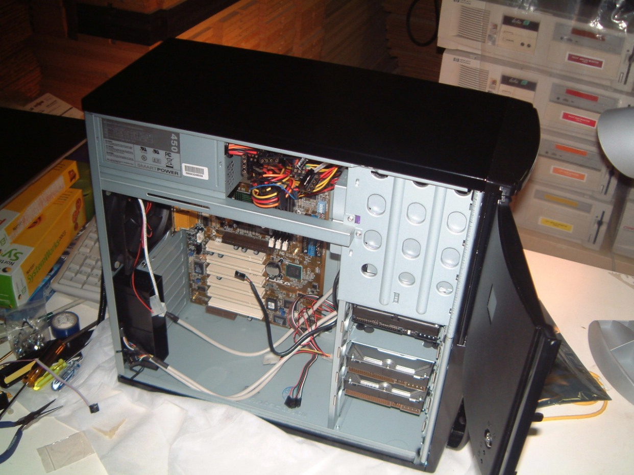
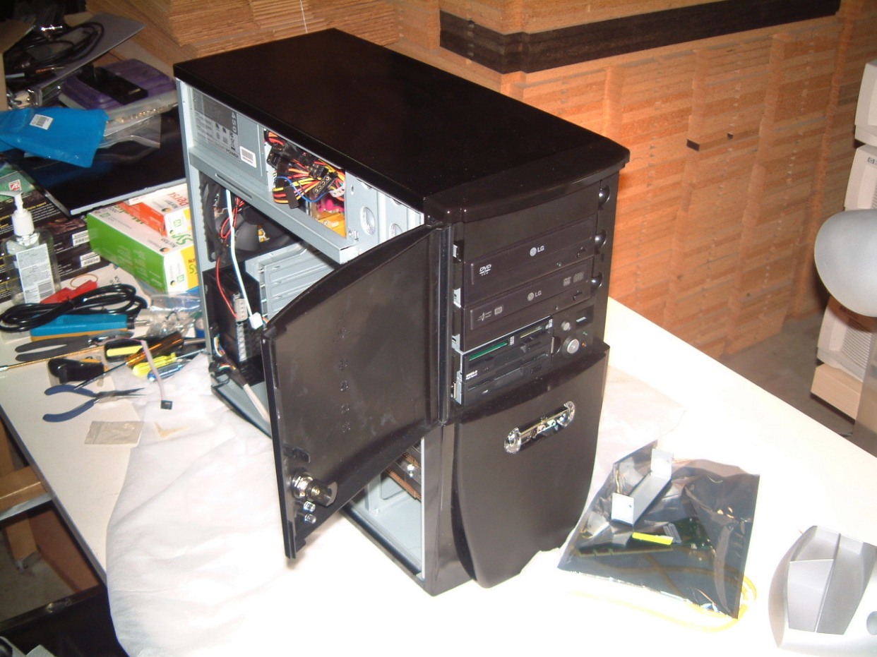
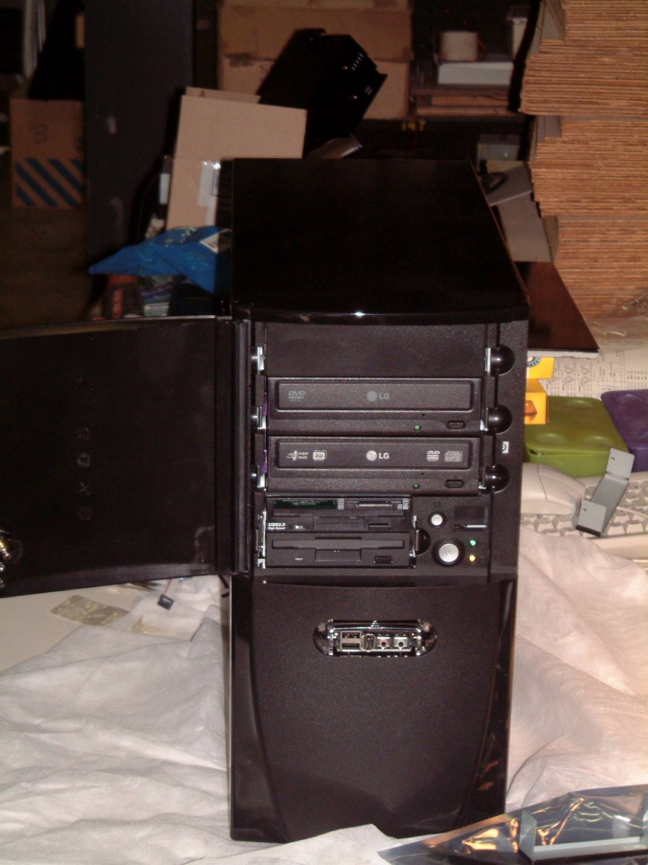
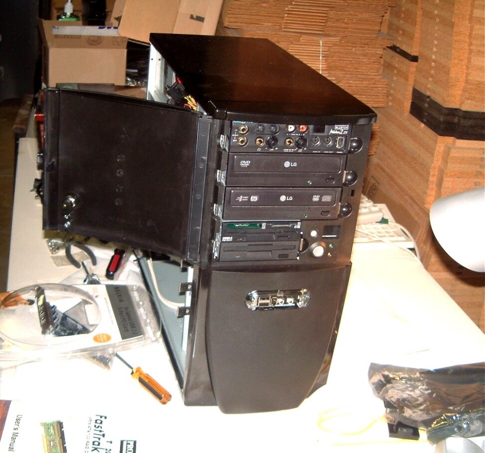 The left shot
shows the case from the side, the next shot shows the diaognal view of the case and the ine to the right is
head on. The next photo was added later after I locaded a spare Soundblaster Audigy
set-up. The mother board has been installed in the case and I will add the
processor and the memory then the ATI card. I will partition the drives then
attempt to install the FastTrak card.
The left shot
shows the case from the side, the next shot shows the diaognal view of the case and the ine to the right is
head on. The next photo was added later after I locaded a spare Soundblaster Audigy
set-up. The mother board has been installed in the case and I will add the
processor and the memory then the ATI card. I will partition the drives then
attempt to install the FastTrak card.
We solved the problem with the First IBM NetVista. It wasn't caused by the D-Link Wireless card but by an interrupt conflict. We had to re-install the ATI all-in-Wonder-Card.
November 14th, 2006
The latest release of WidevieW has a revised start-up system that makes it easier to het the system up an running. Its designed for Microsoft's Flight Simulator 2004 but it can incorporate the things from the earlier 2002 issue. Unlike Flight Simulator X which requires over 15 Gig of contiguos hard disk space even to load, and requires a lot of space to run. There is a more serious problem in the number of aircraft that are available is much less than in the earlier 2004 issue. I was able to get a trial verion of a Cirrus download as well as a 182 Skylane version with a full an LCD based panel. I'm using these on a older Pentium Two Computer for the time being. What will happen next? No doubt, that well we'll have to to install much more memory and switch to Vista to reap the benefits?
G-force FX 5500 3d fuzion graphics card had a problem. Something was wrong with the CD-Rom that came with the cars, We had to download the the correct drivers so that it would install properly.
Then we were able to download the updates for Win 2000 even though it was SP4. FS 2004 installed OK. Thank heavens I purchased several copies of WIn 2000 as well as several copies of Flight Simulator 2004. Both went into the Pentium Three IBM NetVista computers. As I mentioned, I have located two more NetVista computers and if I can locate two more the whole Flight Simulator (except for the server) will operate from these.
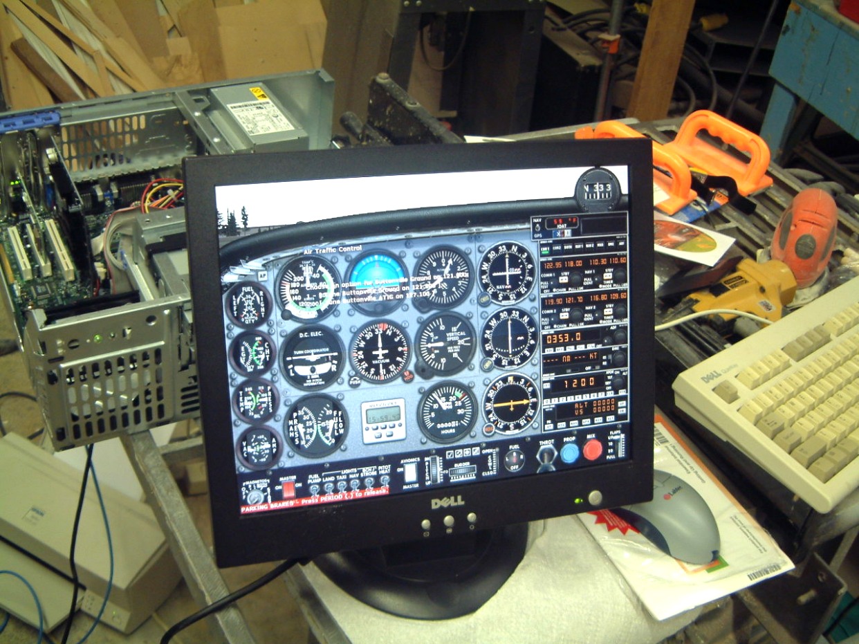
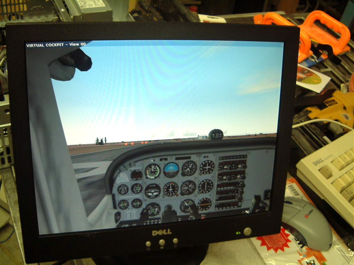 I've had to take over part of the carpentry shop to set-up the IBM NetVistas.
Its quite crowded now. I still have the other NetVista in the rear of my lab, I
still have to get the ATI card set-up. As the wireless card I working,
when I am able replace the cover I can move the NetVista to my home. But this
was not to be!
I've had to take over part of the carpentry shop to set-up the IBM NetVistas.
Its quite crowded now. I still have the other NetVista in the rear of my lab, I
still have to get the ATI card set-up. As the wireless card I working,
when I am able replace the cover I can move the NetVista to my home. But this
was not to be!

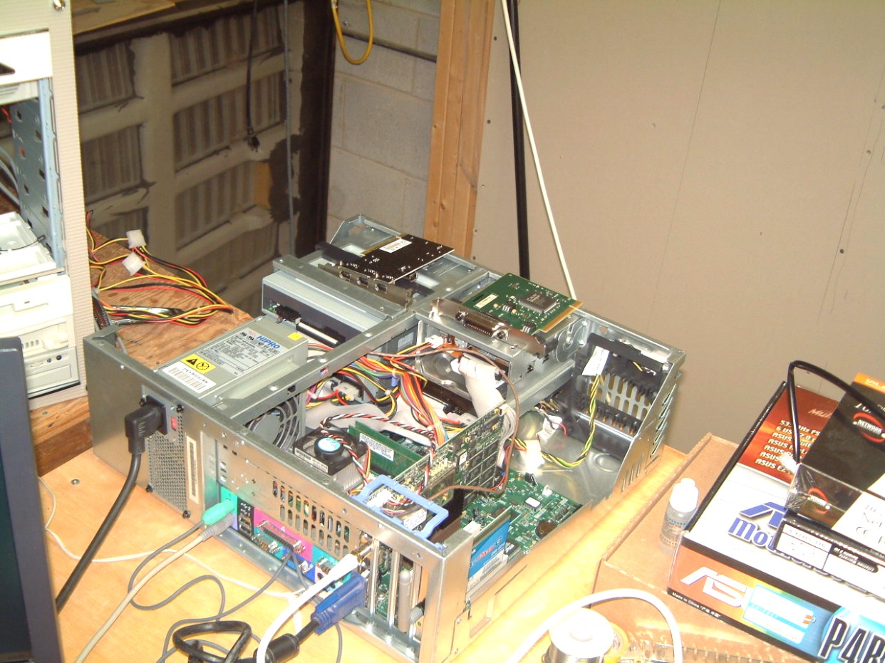 It turned out that the program
enabling the IEEE 488 link was missing. So we pulled the card.
It turned out that the program
enabling the IEEE 488 link was missing. So we pulled the card.
The Compaq computers have small capacity ATI Rage graphic memory in them and as expansion memory isn't available they will be sold to someone who is satified with a three monitor system.
I have found a company that manufactures a rwo-layer transparent flexible vinyl based adhesive film. The outside layer is supposidly sufficiently conductive so that is is immune to static electricity damage. I am waiting for a sample. If this works, my Flight Simulator panel can be overaid so that it can't be damaged by static. The I can install the replacement chips! The Cesnna 177 pilot's seat was upholstered with a cheap fabric covered and it is wearing out. I think it's about time to purcase a snazzy cover!
November 24th, 2006
Another week and we've finally got my IBM NetVista Pentium 3 up and operating properly. I thought that it was the D-Link wireless unit on the rear of the computer that wasn't working. After repairing Win 2000, reinstalling the Firewire card and after pulling out the IEEE 488 card it worked.
 Finally it works. I
can take it home after Ma Bell approves its connection and the DSL is enabled.
Finally it works. I
can take it home after Ma Bell approves its connection and the DSL is enabled.
Back to the Flight Simulator upgrade. We were able to clone two more Western Digital 80 Gb hard drives and another is waiting. Apparently IBM contracted out the hard drives and too many of them failed in extensive service.
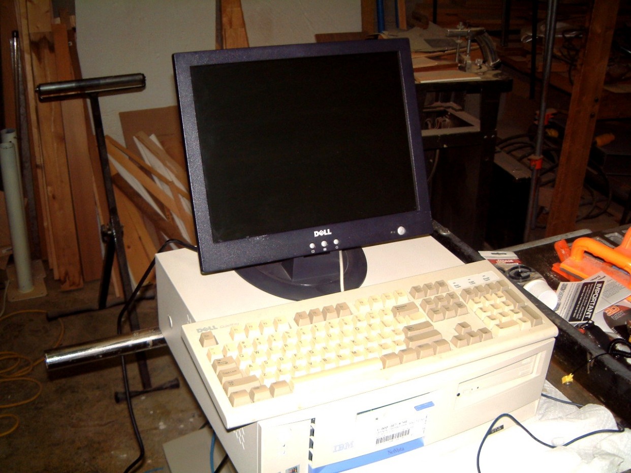 It has been running
for a week with no problems. So I can return it to the 'holding bay' and
do another one! To give you a hint of what too many computers look like when
their being worked over, take q look at this
It has been running
for a week with no problems. So I can return it to the 'holding bay' and
do another one! To give you a hint of what too many computers look like when
their being worked over, take q look at this
.
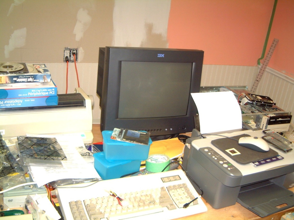
 Out of the picture
are the throttles and a just visible control stick!
Out of the picture
are the throttles and a just visible control stick!
December 28th, 2006
Another change of computers. I will change the operating system on the supposed media room computer from Win 2000, to Win XP Pro. As I have lots of space on the hard disk drive, I can copy most of the essential stuff before switching to XP-Pro. I still have a legal disk of Win 2000 which I will use for my home computer, runninng a cheaper form of DSL. I already bought the DSL (router) and will use a D-Link wireless router to connect the two computers at home via a set of phone line filters to provent the DSL from interfering with the telephone.
I really dislike Microsoft's insistance on making their clients upgrade every so often to prevent hacking. It has forced me to abandon several years of work using the various versions of Visual Basic. Most of the Hackrers, Malware, Spywar and Worms use Visual Basic. I've kept track of all the costs that I've paid Microsoft for upgrades and complete Visual Basic Programs. I was surprised to find out that it has cost me over $5,500 to date, I have not included the months I've spent in learning the needed upgrades.
The so called 'paperless office' is a crock, everytime one of our mamy customers are forced to change their PO and Inventory system it can take us several weeks to correct our 'inteface' to make it compatable, often it can take over twenty five telephone call at our expence to straighten out the system. What really bugs most people I know Is having to deal with a sevice rep, for example in India (Norton) that seems unable to understand just what you want to renew your subscription rather than purhase another version that requires several hours of cleaning up all of the detrius that came with the earlier Norton Stuff.
January 4th, 2007
Well another alteration in planning. As it seema that the Audigy P FX is no longer in production I have to resort to the Soundblaster X system and use a four port Firewire card in conjunction with a five port USB card. This really gets my goat as I had a spare Audigy Platinum FX front panel, cable set and rear sound card with all the installation CD's in a box. Some time during the last fifteen months I had to stop the assembly of the system as the case I was planning to use was defective; 25% of the hardware (includind both side panels) were mismatched. As I repacked the componets that I was intending to use I had more urgent matters to attend to (Under RoHs, we had to scrap all the used nineteen and twenty one inch monitors I was using for the Flight Simulator.
By the time I was waiting for replacement parts, I found out that the case manufacturer had filed for bankrupcy (apparently he was selling fake copies of another well-known computer case).
Another problem occoured, the old reliable 486 computer in our office, had to be backed up via a tape drive. We sheduled the normal weekly back-up in early November, but the drive wouldn't function. It took another month to discover a 'temp' in our office has found a way to add an extra charcter was an 'escape' and wasn't visible on the listing of custumers.It took me a month to find the illegal 'escape's.'
We had to resort to using x-copy to clone the existing hard drive and install it in the back-up computer. So far it seems to work!
Jan 10th, 2007
At long last, the connection cable-set for the three colored output cables to connect to the RCA-type inputs for the power amplifier's have arrived.
 There
is only a .gif available.
There
is only a .gif available.
These are available at::
http://us.creative.com/products/profuct/.asp?category=1?subcategory=16?product=14309
This is listed as "Sound Blaster Home Theater Cable" and sells for ~ $14.95 US + shipping and duty. At that price it's a bargain. We connect the ouputs via a slide-type volume control so the the varying gains of power-amplifiers can be balanced. Be sure that all the outputs ar in phase!
Feb 1st, 2007
After numerous delays we finally got my 'home' up and running. We decided to mirror it rather than striping. We had a minor problem with the FastTrack installaton. We first paritioned the two WD 80Gig drives. rebotted the computer as many times as needed when were re configuring it or adding new components.
Installing and getting the first 330 Gb drive was easy, mirroring the 'slave' took two and a half hours. It has necessiciary to reassign the Drive letter as the software was a bit stubborn.
We first converted the LAN from Cat 5e to 'G' spec -Link wireless. We had two versions of the software D-Link software, neither worked. It took almost an hour to clean up both bersions, reinstalling the Cat 5e software so that we could download thw latest version of the installing 'G' spec -Link wireless. Then we removed the Cat 5e software, next running the wireless installation. This time it ran prefectly.
We are switching over to AVG Internet Security - it comes in three versions, Antivirus, Antivirus + Firewall, Antivirus + Firewall + a comprehensive AntiSpyware. The two year package sells for about $60 US. However we are still using Ad-Aware and SpyBot S?D.

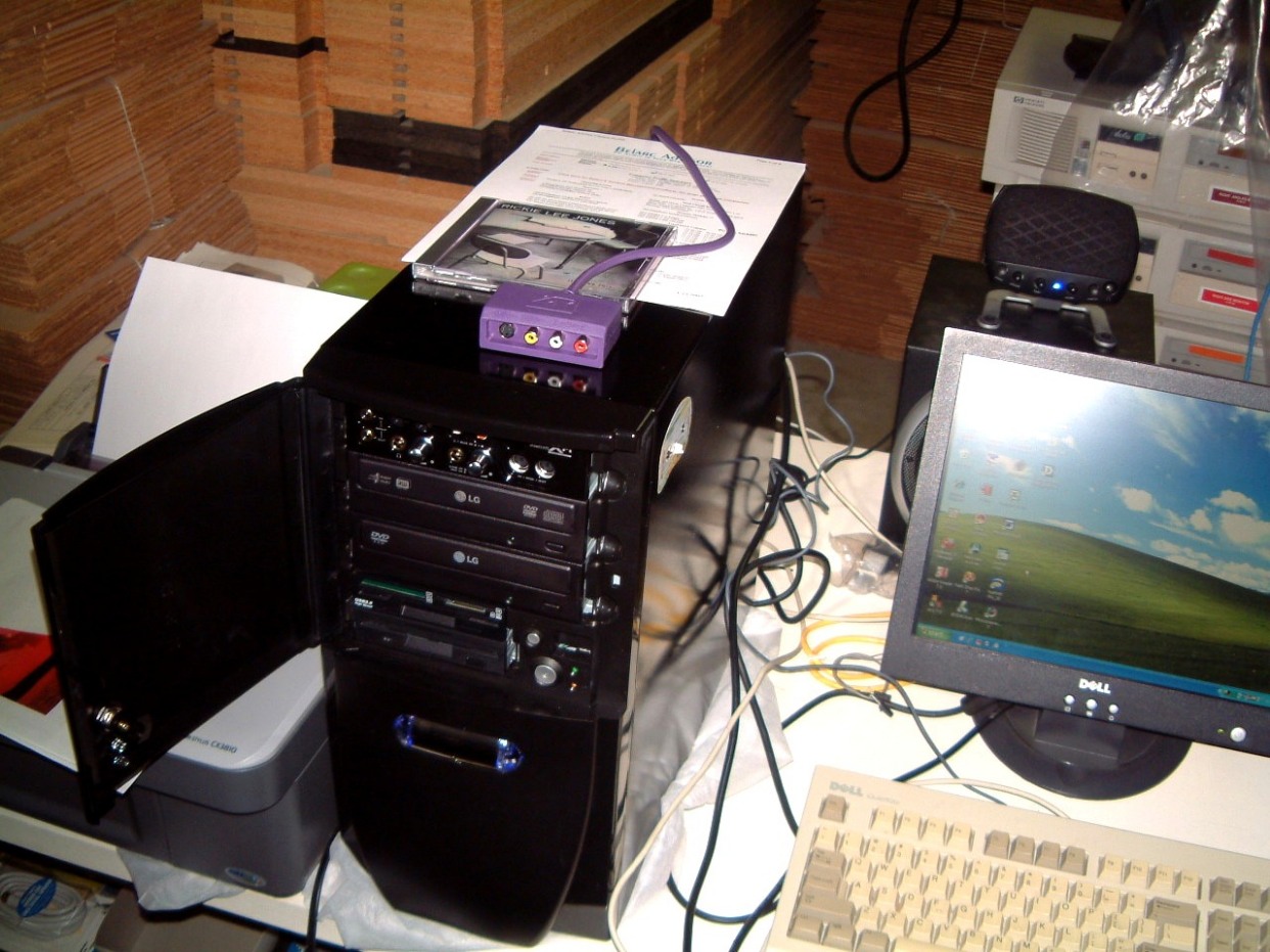 We used
the Antec Sonata 2 case. Using it was a bit tricky as it has some air
ducts inside that have to be replaced after everything else is installed. There
is a short duct that clips over a horizontal opening (the case is lying in its
side) and thos opening is above the cards. This plastic duct snaps in place.
Next is a large and complicated duct with ita end over the CPU (ans fan). The large
fan on the back is a three speed unit. We set it to high. The gloss black case
is very robust; not a case to use if you have a bad back.
We used
the Antec Sonata 2 case. Using it was a bit tricky as it has some air
ducts inside that have to be replaced after everything else is installed. There
is a short duct that clips over a horizontal opening (the case is lying in its
side) and thos opening is above the cards. This plastic duct snaps in place.
Next is a large and complicated duct with ita end over the CPU (ans fan). The large
fan on the back is a three speed unit. We set it to high. The gloss black case
is very robust; not a case to use if you have a bad back.
Feb 8th, 2007
Its as cold as Biliy-be-Jeebers, on Wednesday the Celcius tempersture was -22 and the wind chill was houvring (shivering) beween -33 and -34 Celcius. The flouescent light were flickering. The line voltage was as low that the PBX on our phone system browend-out twice. In the rear of the unit next to us, we're waiting for the cold water pipe to rupture.
March 9th, 2007
As the weather outside our plant dropped to -26 degrees Celcius last night, we were beset with groaning sounds as the steel roof contracted. Every sudden contrction produces a very loud sound.
To add to our grief the amount of spam has tripled since last year, We are forced to run MailWasher Pro three times a day. as well as using Ad Aware as well as Spybot S?D three times a week.
It's with moderate amusement that I note the numer of new computers running Microsoft's Vista Operating System and the plofiteration of 'fixes' already offered.
The dayton-wright URL is receiving lot of 'hits' every week and we receive inquiries about when are thr new Dayton Wright ESL's going to be released. We are aiming for the late fall 2007. We are storing the parts in our Newkirk Road plant for the time being and as we are increasing the production of Stabilants we are running out of space.
The latest Win XP Pro computer (the one built for use at home) has had a couple of attacks that sneaked past my firewall. I ran the updated AdAware and blocked several nasties that attemped to hijack the computer by installing a keylogger. When I ran Spybot S?D it cleaned out the rest of the ceap. We installed the Avant updates as well on four computers. They allow selection of a lot of extra's. More later.
May 3rd, 2007
Busy does not describe it, I had to revise some software I wrote in 1999. Locating my notes (which were filed in 2003), was difficult as they were on fan-fold paper, that was very dry and on sulfide stock which made brittle! Now when you consider that the final program print-out was four and a half inches thick, locating the essential 29 lines (scattered throuhout the program) was difficult.
Enough! As I noted, we had to buy 7 copies of FS 2004, and having to have disk four in place in all 7 computers was a real drag as if one of the disk 4 was accidentally interchanced, weird stuff drove me nuts. We located a Disk Four 'patch' that worked.
Well a week ago I installed the DSL filters on the normal use telephone lines a home, leaving the computer line free. Were waiting for approval from our phone company to enable our DSL service. They have to assign an IP addess and therefore we have to wait. As we are rarely there during he phone companys normal buisness hours, it has been problem. Several times we took a day-off only to get called two days later asking why we were not at home when they were ready, This callous indifference to the public seemes to be the hallmark of large corporations and gouverments everwhere.
I had to
intstall a telephone with a DSL filter. Here it is:
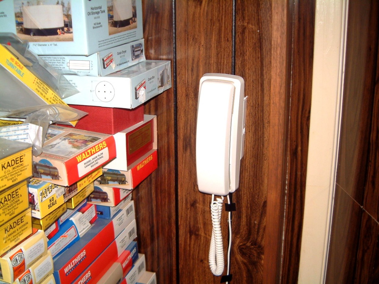
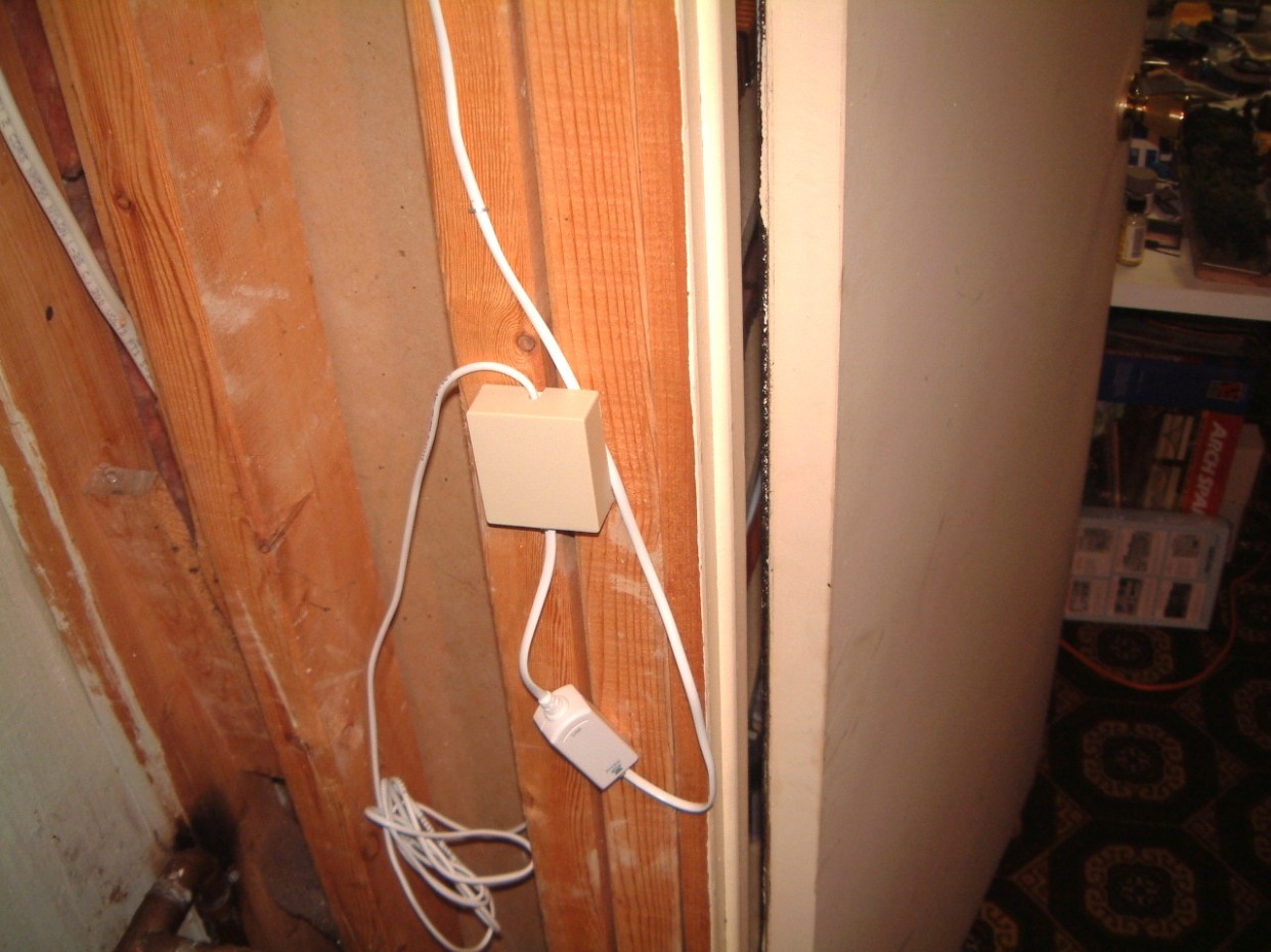
I had one
difficulty, the I could not reach the other telephone wiring. I need a slimmer
tech with longer arms!
May 27th, 2007
More delays of the updates. Were hit by an attack that tried to disable some of the security camera's in our plant. Fortunatley I spotted it right away, it affected only the horizontal synchronization at first, then it completly disabled one camera in the central area of the plant. We traced it back to a weird Spybot that imbedded itself in the disguise of a minor Trojan Horse leaving the camera-bot behind to be activated, probaby be chance!
Getting rid of it proved simple. We ran the last update, it dicoverd the bot, however to remove it was a bit tricky as it was imbedded in one of the video files; running Spybot S?D on startup cleaned it out, leaving a nasy messsage telling he that it required a total reinstallation of the computer's operating system.
It's not true, stopping the cleanup, and re-running the loading of the system again gets rid of the bug, as the update's trap and quarantine it.
July 31st, 2007
I have been occupying myself in installing the link to Hydrospace Deveopments Ltd.
This took far longer than I anticipated. Most of the diving suit stuff was either stored in the rear of our plant, in our home or in a stoage locker. Bits and pieces were on loan, sqirrled away, misplaced, or even stored in one of those safe places that only a wife thinks that a husband can think of looking in
Therefore, I have been adding stuff whenever. my defective mind, frustrated beyond belief, can only be grasping at straws, think of looking. I have reams of drawings, renditions, some publications and a hell of a lot of "Didn't you think of looking there", in a nece turn of phrase. Most of the drawings I need, are kept in a heated mezzanine at the rear part of our plant! Some things are still painful to think about!
Therefore whenever my blood pressure is too low I have an instinct towards picking at scabs. I am told that a good bloodletting was needed. After all, it worked in the eighteenth cenrury, why not now?
August 17th, 2007
After innumerable delays I finally junked the old CRT 22 inch monitor replacing it with a 22 inch (wider) monitor.
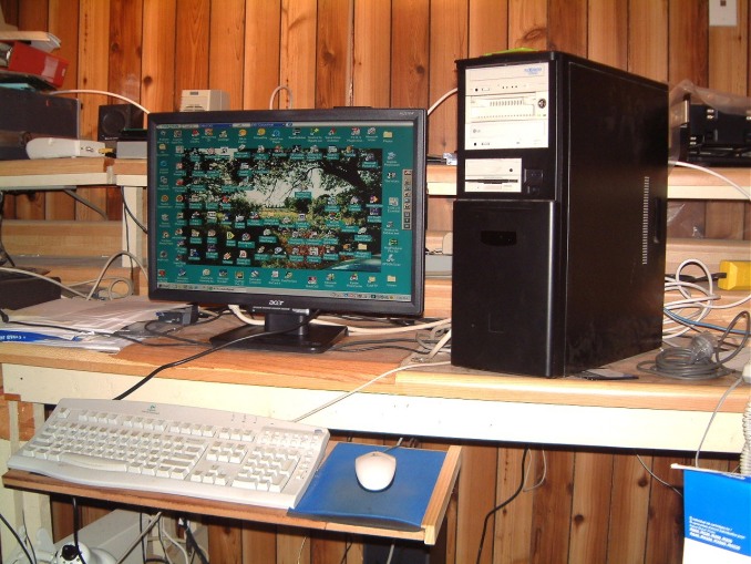 As this is closer
to my keyboard, it seems easier to use; much less head bobbing.
As this is closer
to my keyboard, it seems easier to use; much less head bobbing.
It was time to replace the smaller CRT monitor that I use for transferring s-video to DVD's.
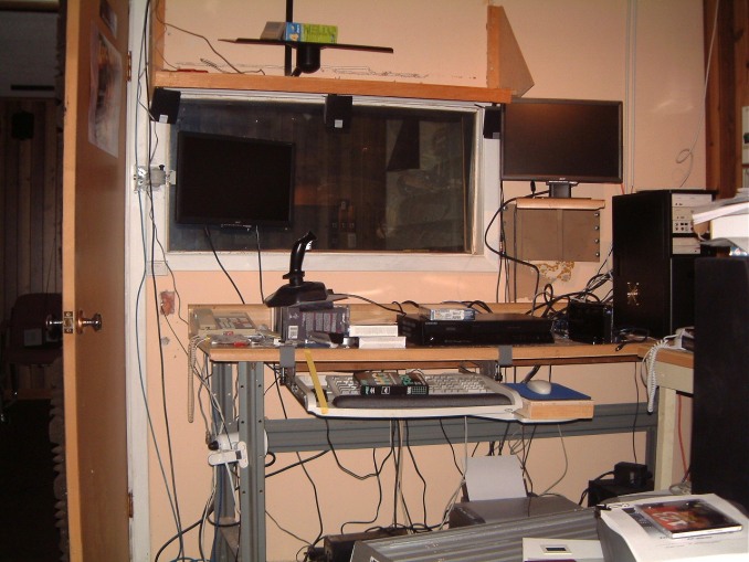 The previous change
worked well and the process of using an older s-video tape player to both edit,
insert the transitions and make additions to the sound was nerve wracking. This
way I can use the DVD player as the source, stop it while I add transitions
etc.
The previous change
worked well and the process of using an older s-video tape player to both edit,
insert the transitions and make additions to the sound was nerve wracking. This
way I can use the DVD player as the source, stop it while I add transitions
etc.
September 1st, 2007
We could not get the S-Video to DVD burner to work properly. It read the S-Video tape into memory at a moderatly fast speed; and seened to transfer it to the DVD+R at a normal speed. Then something was wrong as the DVD format couldn't recognised on playback.
The new Samung DVD-VR355 has a very complicated manual. As an example, it doesn't say just what type of monitor is needed. In desperation we tried composit video before we were able to get an output on the screen. Then I had to try several DVD-R disks until it would initialize. The manual seemed to baffle the experts I retained. It wans't that it was too complex as it was very poorly organized.
I still do not know why no computer we have available will recognize the DVD-R disk.
September 14th, 2007
Another urgent task had to be done before I could re-configure the DVD transfer.
The the door to our furnace room at home was the way it was when we moved in
over 25 years ago; now it has to have two grilled vents installed at the upper
and lower part of the door to prevent, I supose, any accumulation of carbon
monoxide in the furnace room. So to make sure, I decided to install a carbon
monoxide detector underneath the lower vent.
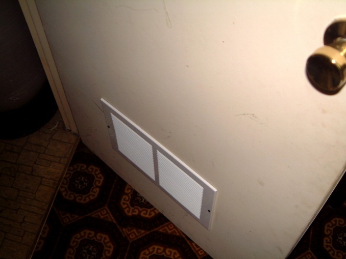
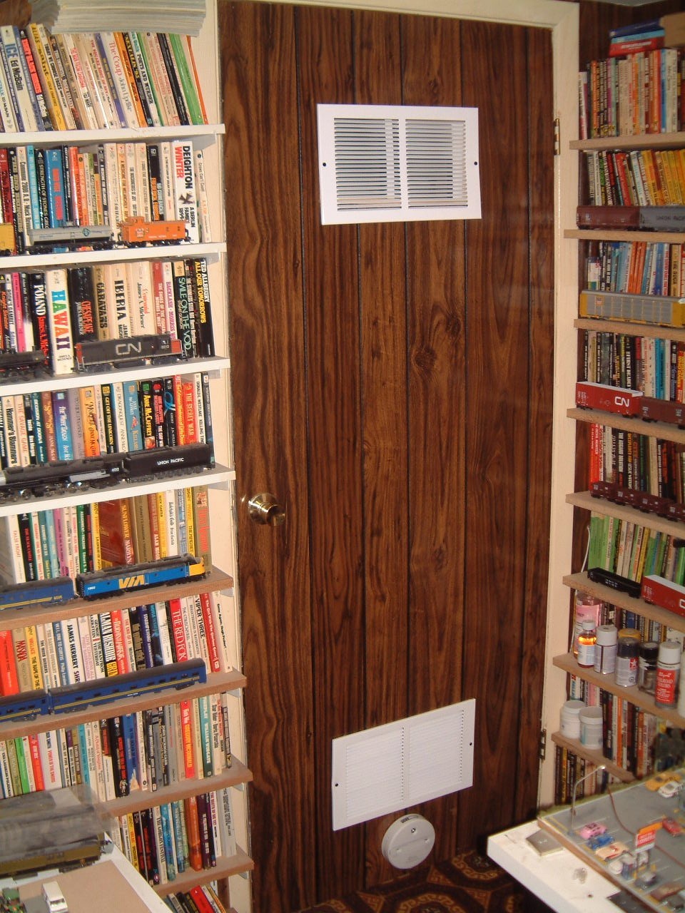 As you can see, even my basement room is
used for HO gauge models as well as thousands of books.
As you can see, even my basement room is
used for HO gauge models as well as thousands of books.
September 18th, 2007
More work at the plant; we finally got our air compressor hooked up. In 2004 we were advised that it had to be re-located to the extreme back or our plant. This involved using a piece of two inch conduit to support and carry both the 10-3 BX cabling as well as fifty feet of heavy air hose from the rear of the plant, up to the room where we run the actual production. I took three month to get it done. However, although the end-capped air hose tested OK (the hose wasn't yet onto the room where we needed the compressed air), nor was the 10-3 BX wiring connected. I needed another electrician to ring through the BX as some of the ID stickers on the breaker panel had been removed during the 2004 cleaning it was a problem. Well, it finally got done and I was finally able to test the compressor properly.
I must explain that I had been using a small portable Bostick unit that was purched for use in our summer cottage in Minaki. I pressed it into use in the revamping of the Media room in our plant.
The completion of the actual compressed air hose took me a day as a temporary fitting blew off during the 170 pound final testing. One of the hose clamps was a bit loose; and wouldn't you know it, the location of the fitting, was almost impossible to get at to. It was where I intended to run compressed air into the machine-shop area.
We have to allow four to six meteing units to be used, within the next three to five years. The distribution piping has to be connected to one unit within a week. So I have to run the pipe along two and a half sides of the room and allow the installation of at least three pressure regulators on the pires. I also have to install a small reserve tank to even-up the flow from the air compressor; this means that I have to install a moisture bleed-off valve; probably in a corner by the eye wash fountain.
To continue, the larger air compressor hadn't been used since February of 2000 and it was dusty. Something else was missing; the filter and oiler had been removed; why, I didn't know. It took several hours of searching to locate these attatchments. Then I was able to see why they had been removed. The larger threaded brass pipe was broken off and a smaller one substuted. One of my staff (circa 1997) bypassed the assembly and connected the output from the pressure reducing valve directly to the valve coupling.
Back to home depot to locate the two needed adaptors (one for the air
compressor outlet and the second one for the after the assembly. As the air
compressor outlet was too close to the assembly, an extension was needed.
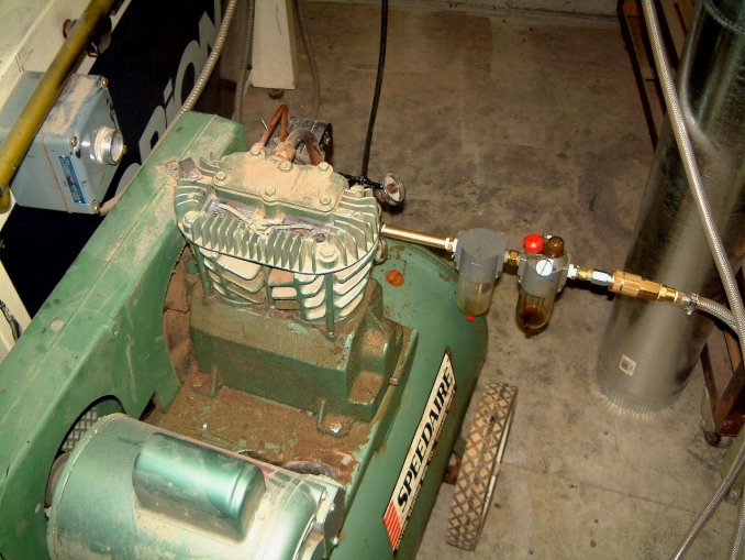
Then I had to run a high pressure (well, 200 lb test), with two screw on clamps
to secure the hose to the barbs.

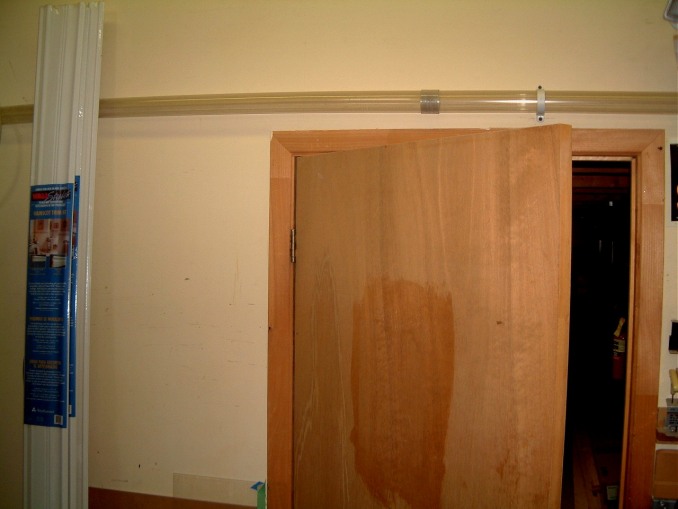
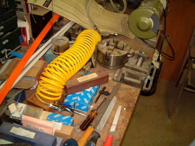 This is OK for now. I'll
rig an overhead support for the air hose.
This is OK for now. I'll
rig an overhead support for the air hose.
Next step is to make a setup for the compressed air powered metering valve. These operate on 30 psi and are stainless steel. I built epoxy coated wooden supports for these in 2002, but I wasn't able to use the system until late September. Now I have plumbed up the brass fittings on the prototype unit.

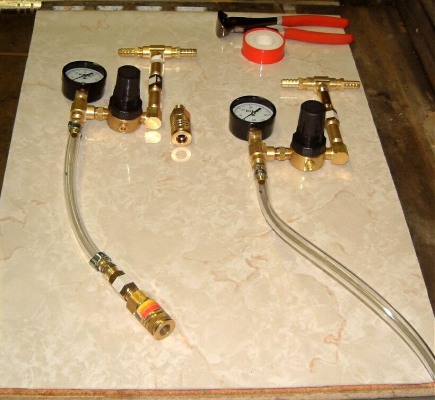 I have to make mounting brackets for
these. I can obtain mounting rings for the valves; and can fabricate sheet
metal fittings that can scew into the wall itself. I was able to use a lower
pressure tubing for the connections to the mrtering pumps and as it is very
flexible it will enable the units to be moved easily.
I have to make mounting brackets for
these. I can obtain mounting rings for the valves; and can fabricate sheet
metal fittings that can scew into the wall itself. I was able to use a lower
pressure tubing for the connections to the mrtering pumps and as it is very
flexible it will enable the units to be moved easily.
October 11th, 2007
Another task in the carpentry shop had to be done before it got colder there. I had purchased a 220 volt wall mounted fan heater sometime in the fall of 2002. As you mifgt hafe forseen, I put it away in the 'stack - storage area' on the back of the plant; and forgot about it. In October, we had an unexpected cold snap, and it became too cold to work there. The other company in the adjacent unit used the major part of their space for 'dead' storge. When they moved to the front area of the building complex, they didn't have any reason to heat their storage space above 50 degrees F. Our heating bill increased by a factor of 1.45 (adjusing for the cost of gas).
Therefor I had to dig out the heater or get used to clinking whenever I walked.
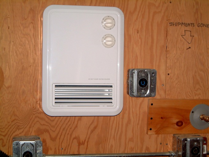 I was able to mount it adjacent to the
Hubble outlet for the belt sander, both are 220 volt. As I had to fabicate
several eight foot lengths of wooden mounting for the mountings of the 30 psi
metering pumps, it was easier to make, sand and paint all at the same time. I
have showed you the fittings already and I have to wait for the plastic nuts to
mount the Watts regulators.
I was able to mount it adjacent to the
Hubble outlet for the belt sander, both are 220 volt. As I had to fabicate
several eight foot lengths of wooden mounting for the mountings of the 30 psi
metering pumps, it was easier to make, sand and paint all at the same time. I
have showed you the fittings already and I have to wait for the plastic nuts to
mount the Watts regulators.
I bought a laser level so that I could mount them at the same level. As I have to install more cabinets within couple of months this made sense.
November 18th, 2007
Almost a month has sliped away. I had to make several sets of brackets to mount several air operated dispensers. These had to be powder coated with epoxy. These would have a regulator and a pressure gauge, and would be mounted wherever we needed a supply of compressed air.
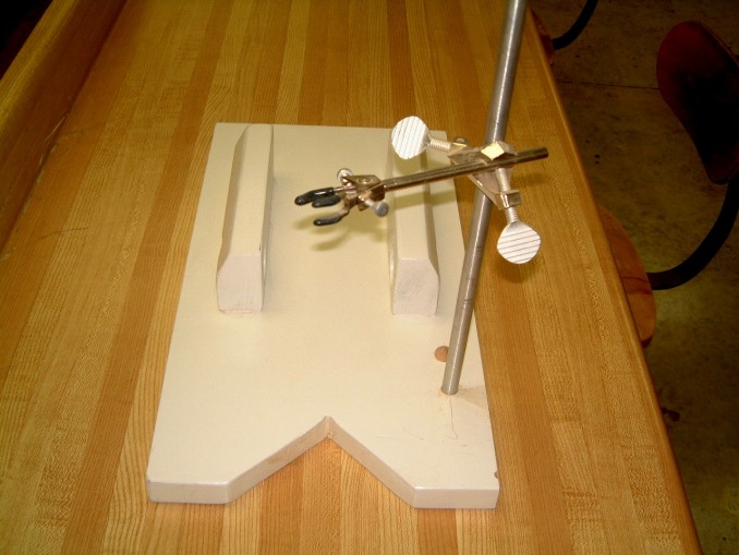
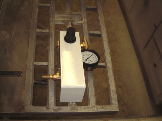 At the left is the vertcal rod mounted on a wooden base; not yet shown is the
metering unit. Next (upside down) is the backet that is connected to the
fibreglass reinforced air distribution hose.
At the left is the vertcal rod mounted on a wooden base; not yet shown is the
metering unit. Next (upside down) is the backet that is connected to the
fibreglass reinforced air distribution hose.
January 21th, 2008
After several weeks passed, it was about time for an update. In January we were hit by an extremely heavy snowfall, that changedto freezing rain and black ice. We were unable to get to our plant for three days. Then the temperature increased so much that the four feet of snow melted down and people started to wear lighter garments.
However the mild weather didn't last and we were hit once more with a heavy snowfall. Once again the highway accident report passed well beyond 1100 a day. The majority were minor; some were worse. Even though the OPP begged drivers to slow down there were the usual idiots (most driving SUV's) that didn't seem to think that the warnings did not apply to them.
I learned to drive in Winnipeg where heavy snow and white-outs were common. The rule was 'never drive past your visibility and always expect blowing snow to cut your visibility with little warning - slow down before you can't see 150 feet ahead). Then proceed with extreme caution as somebody might have jammed on their brakes and slid into another vehicle. We learned the hard way that never jam on your brakes but attempt to steer around another vehicle. So long as you are able to control your vehicle you might be able to survive with minor damage.
I had installed a tow hook at both the front and rear of my vehicle as many times when I encountered a car that had either run out of gas. Or the driver had fallen asleep and left the road. I should say that many times I had to drive over a thousand miles.
At times I had to drive in icy conditions on major highways. I learned to expect the unexpected such as a tractor trailer that had jacknifed. I made it a game to select just where I might be able to leave the highway if I had to. In 1968 I was driving down from North Bay when I saw that a tractor trailer that had jacknifed. I steered off of the highway into deep snow. I was only shaken up. Another tractor trailer about two miles behind me saw where I had steered off the road. I always carried a spotlight with me, the type that has a rechargible silver cell that can be plugged into the cigarette lighter. I was able to open the passanger's side door and climb up to the road. The tractor trailer had a long chain with him and was able to haul me up to the highway.
There wasn't any damage but the engine compatment was tightly packed with snow; so much that the imprint of the underside of the hood was visible. But after the snow was removed the engine started!
Here are some more shots of the 'lab'.
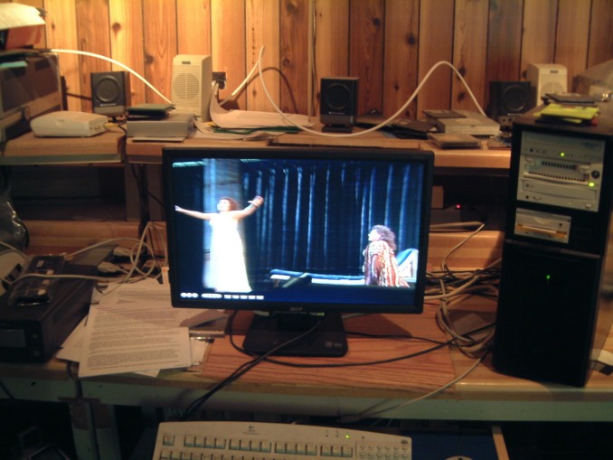
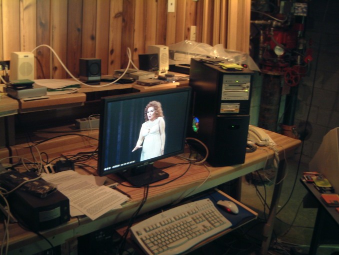
And of the 'media room'.
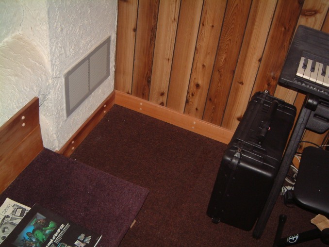
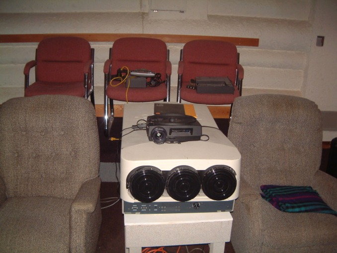
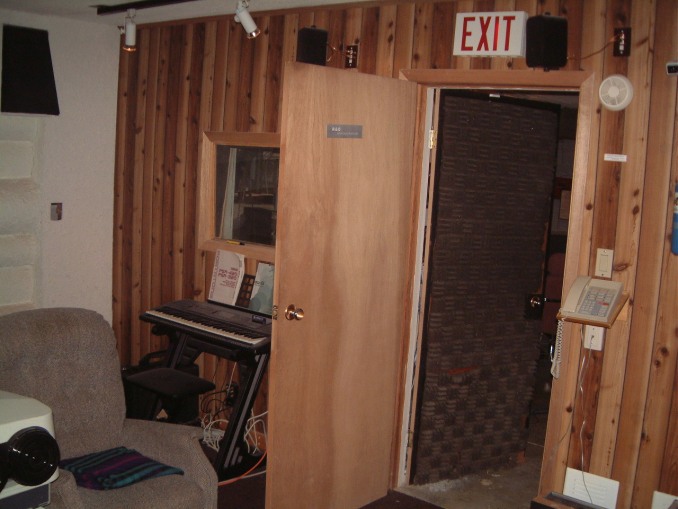


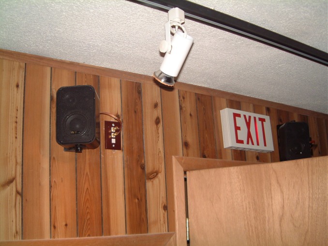
Feburary 7th, 2008
As I said the snow in February was very deep.
 This mound was on the corner.
Feburary 16th, 2008
At long last I have been able to sort-of-seal the opening in the corner where the sprinkler stack runs up from the concrete floor up to the pipes that supply the water to all the sprinkler heads all over the plant. Unless the two folding doors would close together, during the coldest part of the winter, the temperature in this area would never rise over 59 to 65 degrees F. One problem was that a hell of a bunch of DSL, TV, and other wiring dropped down from the mezzanine to the concrete floor. Month by month I would reroute these, whenever I was able to devote several hours. But, the other tasks had to take precedence.
This week I'd had enough. The first item was to relocate the dimmer for the overhead light bar (which was up on the wall close to the folding doors) onto the surface of work bench (see photo below). Then, one at a time I hauled all the cables up and rerouted them. There is still a DSL plate on the wall, but I have to move a four drawer filing cabinet so that I can drill a clearance hole for the DSL jack
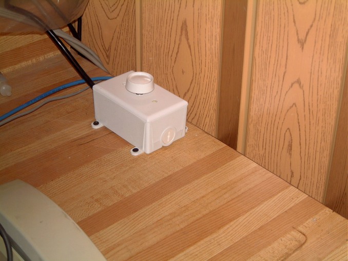

![]() But when the folding door are opend
so that the old dimmer can be removed and a plate with the Heyco cable bushing
installed the circuit breaker has to be shut, and the corner gets too cold to
work using an extention light! The photo on the right was taken the next day. I
had to use an offset bracket to screw onto the metal box as the location of the
cover plate screws were less than the spacing on the box mounting. I reamed out
the center of the cover so that the Heyco bushing snapped in place. Heyco has a
custom set of pliers to force together the parts of the bushing while it's
snapped in place. By the way, I have a special diagonal split blade screwdriver
that when the slide is moved towards the screw locks the screw tightly
so that it doesn't fall off. When
I have to use a screw 9 to 12 inches away from the plate (especially in a case
such as this) the clearence is so tight as to make this type of job impossible.
But when the folding door are opend
so that the old dimmer can be removed and a plate with the Heyco cable bushing
installed the circuit breaker has to be shut, and the corner gets too cold to
work using an extention light! The photo on the right was taken the next day. I
had to use an offset bracket to screw onto the metal box as the location of the
cover plate screws were less than the spacing on the box mounting. I reamed out
the center of the cover so that the Heyco bushing snapped in place. Heyco has a
custom set of pliers to force together the parts of the bushing while it's
snapped in place. By the way, I have a special diagonal split blade screwdriver
that when the slide is moved towards the screw locks the screw tightly
so that it doesn't fall off. When
I have to use a screw 9 to 12 inches away from the plate (especially in a case
such as this) the clearence is so tight as to make this type of job impossible.
Next in line was the installation of four receptical outlet down on the southern wall of our plant. I have grown frustrated at the difficuty of getting my old Windows 3-1 computer running. As the area is allready jammed with five computers of varying sizes and capabilities getting this older one working might seem a bit redundent however I have and old air-traffic-control system installed on this computer and - in time - I may be able to make it work with the WidevieW flight simulator program.
The four recepticals are mounted on a plywood wall in the lab area of our plant. Well, the fabrication did not seem much of a problem. I had all sorts of plastic conduit in our plant as well as a host of electrical mounting hardware. I cut a piece of Carlon 3/4" conduit to 35" in length, cementing it to the top of the plastic box.
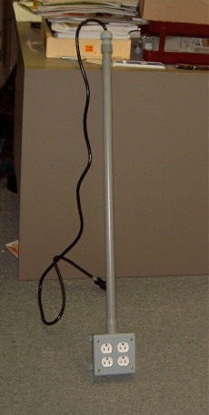 This is what it
looked like in my office. The electrical extention cord is clamped in place at
the top leaving plenty of slack for the wiring inside the box. I had the
usual problems in bending the 12 gauge wire to fit inside the box until I
realised that the 12 gauge wire could be seperated from the flexible extention
wire. The latter three wires cound be connected to the extra binding screws on
the terminals and the surplus wire pulled up when the elastic bushing was
loostened. By the use of drywall screws the assenbly was easy to mount on
the plywood. However; I still have to mount the computer case in a verical
podition at the side and the underside of the monitor table. The ^?$*@%
19" monitor is very heavy; I am sure that I could locate a flat screen
monitor that could replace it.
This is what it
looked like in my office. The electrical extention cord is clamped in place at
the top leaving plenty of slack for the wiring inside the box. I had the
usual problems in bending the 12 gauge wire to fit inside the box until I
realised that the 12 gauge wire could be seperated from the flexible extention
wire. The latter three wires cound be connected to the extra binding screws on
the terminals and the surplus wire pulled up when the elastic bushing was
loostened. By the use of drywall screws the assenbly was easy to mount on
the plywood. However; I still have to mount the computer case in a verical
podition at the side and the underside of the monitor table. The ^?$*@%
19" monitor is very heavy; I am sure that I could locate a flat screen
monitor that could replace it.
Another minor problem is just a nuisance! I have been attempting to add upgrades to using Pinnacle Title Extreme without using Heroglyph 2.6.26. There is nothing with the purchase to state that it is an add on program. Well, I found out that Pinnacle 11 cannot run it without ProDad (from Heroglyph). Of course the add-ons cost much more than the Pinnacle 11 Pro!
Well, I should have expected as much. A lot of manufacurers make much more from the add-ons than from the software itself. Take (as an example), printers. The printer itself is quite a low cost item, but the ink cartridges are expensive!
March 3rd, 2008
Time to upgrade once again. The video's I have been editing are a bit fuzzy as the quality is only 48% of nomal. The video ram is way too low. OK, I hope that the ATI Radeon HD 3870 will correct that problem. It's designed for Direct X 10.1 support with 512 Mb/MO GDDR4 - full HD 1080p video playback. However I will have to change my monitor to a 24 inch unit using a different connector. That doesn't pose a problem for the Barco projector.
Also, I'll have to procure a BlueRay burner. So far, the best one seems to be
the Plexor.
 At an estimated
price of $800 US, it's still very expensive; however it will handle DVD+R DL
manufactured by, for example, Memorex. Plexor has an excellent reputation.
Remember these DVD's do not have to be so expenive as a two hour program can be
burned on a less expensive media. So for the time being I'll stick to the
Yamaha burner and the Sony DVD rom player. A possible and less costly
alternative might be the new LG burner. All the specs havn't been released yet,
but if it's OK, I'll use it.
At an estimated
price of $800 US, it's still very expensive; however it will handle DVD+R DL
manufactured by, for example, Memorex. Plexor has an excellent reputation.
Remember these DVD's do not have to be so expenive as a two hour program can be
burned on a less expensive media. So for the time being I'll stick to the
Yamaha burner and the Sony DVD rom player. A possible and less costly
alternative might be the new LG burner. All the specs havn't been released yet,
but if it's OK, I'll use it.
March 18th, 2008
This upgrade seems to imply one more Computer that will work on true HD specs. This requires a double core Pentium with a different motherboard that can run XP Pro with as much memory as the motherboard will accept. A terabyte of hard disk is now easy. The 2x Radeon seems to have problems as it may be two fast for the software. This computer will cost about $1,600 to $2,200 US. As I already have 35% of the parts I may be able to reinstall the programs that I have (over $900 US from Pinnacle alone - 45% have never been used. I sent Pinnacle an E-mail and have not received a reply in 6 days.
We have had server problems on and off for the last three weeks. That may account for receiving twice the usual amount of spam over a month and a half. That might account for our server being unexpectedly off line. Come to think, it might also be the reason for Pinnacles tardy responses.
April 9th, 2008
Delays happen. There Is another burner that will burn Blue-Rays and TwoLayers; it will read HDTV's, DVD's CD's etc., as well it lists for ~$430-$450 US.
So In March I placed an order. We finally received the instruction DVD from Pinnacle. However it was for the Version 10 release. Damn; I placed another order for the Version 11and am waiting for it to come, I sent a fax to Pinnacle stating that there seem's to be no way that you can alter the Video attributes except when you are using a video camera as the source for the video. Altering these attributes seems impossible when you are using a DVD as the signal source. So I will have to wait for Version 11 unless Pinnacle responds to my fax.
The people building the new machlne are waiting for the arrival of the new burner. Thank heavens that there extra serial cables for the SATA stuff.
April 20 th, 2008
The Pinnacle stuff is late and there's no tracking number any more on International shipments. After months of frustration, I find that I can obtain the latest Pinnacle release from TigerDirect in Markham, Ontario. But they don't carry it in stock, so have to order it from Pinnacle!
I hate being jerked around by software suppliers, now Pinnacle will be ranked along-side Microsoft. I used to use Foxpro in the dos version. Then Microsoft announced that a Visual Basic version was being released and tje upgraded would be available at a heavy discount to customers that had been using the Dos version. All that was needed was to purchase the new version and send in the receipt for the Dos version to get a substantial rebate. Bull#?#?$! It never happened. All the dreck I got was that for some obscure reasion, (such as I had to install it on the second Thursday of the month having an eclipse of the moon!), to qualify and ~~~~~~~~!
I have over $2900 of Visual Basic software sitting on the shelf in the back of my workshop. As soon I am competant enough to use it, another version is released. One problem might be, that it lends itself to compose 'malware'.
May 4th, 2008
Pinnacle finally delivered both the training manual for Ver 11 and the complete software packsge.
Now for the relay rack cabinet I wanted. I had to go to there new warehouse several miles North of Richmond Hill. It was worthwhile. I obtained what I needed. There was no top so I made one out of G1s Plywood and used Gorilla Glue to attach it to the cabinet, clamping overnight. Then I sprayed it with a black wrinkle enamel. As there were no castors I found four in Home Depot. The cabinet had a recessed skirt that was wide enough to accept castors. I had to elevate the cabinet skirt a little over half an inch so that it was 3/8 th of a inch above the carpet on the elevated platform at the rear of the room. I cut four rectangles out of medium density board trimmed to fit the mounting plateof the castors. I drilled the set-back to attach the castors using 1/4 20 machine screws. I will spray the rest of the cabinet when its warm enough fir the paint to dry properly (it's about 50 degrees in the carpentry shop today); too cold to work in comfort for more than an hour. Dammit, I thought that I has a set of spin-tights that would fit the nuts. I don't so I'll have to dig out the socket wrench set. It will have to wait for another day.
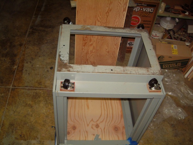 This Relay Rack will house most of the power amplifiers save for the two Phase
Linear 400's I will use for the Sub-Woofers.
This Relay Rack will house most of the power amplifiers save for the two Phase
Linear 400's I will use for the Sub-Woofers.
These will be located at the rear of the 'tank room' under the high platform covering the filter and pumps as well as the Safety Shower and water storage tank. (We didn't want to cut a trench in the concrete floor to carry away the water from the Lab Sink, Eye Wash and shower. So we ran an elvated line connecting it to the bathroom stack where it ran down the under the Gyprock wall for the men's bathroom.
One problem is still stalling me. Because of the smell of the black wrinkle enamle is so strong, I have to wait until the weather is much warmer when I can move it outside to the parking lot at the rear of our plant. Then I may be able to use bricks to hold down a large spread of vapor barrier. But only if the wind is not too strong. the 4' x 6' sheet is somewere in the rear of the plant. I think that it's one of the six sheets that is standing vertically just inside the loading door. But I am still to busy making certain that I have enough paint to complete the task. I have already cleaned out the nearest Home Depot and I am still to busy to try another one; the price of gasoline being as high as it is now. The stock checking is sometimes unreliable!
I still have to fabricate a panel for all the input potentimeters needed to balance the system. I had well over three dozen small VU meters and over 50 Penny and Giles slide potentiometers in the stock list dated August 15th,1999. All were well packed when I put them away for safe keeping up on the rear of the mezzinine, right beside some mixer panels and the channel and output inserts. All of them are there which makes me think that one of the several part-time staff took them. Nobody would know where I put them unless he saw me decending the stairs. The mezzinine was always off-limits to the part-time staff as we kept all the XIM 10/11 interface units stored up there. Well, live and learn!
So I'll have to make do with rotary pots and, pehaps hooded channel reversing switches (to prevent fiddling around). I am sure that I have at least a dozen of them somewhere!
More frustration! I'll never go to a Home Depot Location where the clerk was new! His boss took a look at the Allmost Black Wrinkle Finish spray can. I told him that I can't use it to paint a large steel cabinet because if the very strong smell. Therfore a quart of flat black TremClad wound be fine as a primer. Then, if I had to, I'd take it outside to spray a thin coat of the allmost Black Wrinkle Finish spray. It would cover enough surface to look perfect.
Here is where it began to get strange. The clerk didn't understand what his boss told him. First he took me ro a shelf of Deep Tinting Base. I attempted to explain that this was not flat black TremClad primer. He said that was what his boss told him to get. I waited until his boss returned snd handed him the can of tinting base. He said that it as a latex paint wouldn't work; the clerk said 'I told you that!. His boss said, 'Go and get a can of Flat Black Primer'. he came back and stuck the can in the shaker to mix it Then he placed the can on the bottom of the Home Depot Shopping Cart with all of my purchases. When I got to my van, I opened the tail gate and placed the rest inside the van. Then I noticed that the new clerk had given me a can of Gloss Black TremClad primer. So I took it back, waiting for ten minutes for the clerk to give a return credit. I took the cart back to the paint department and told the boss that the new clerk had given be a can of Gloss Black Primer. He sighed and took me to where the Flat Black TremClad primer was, and put in the cart. The clerk was there and asked 'Did you foreget that needed something else?' I had to leave before the explosion!
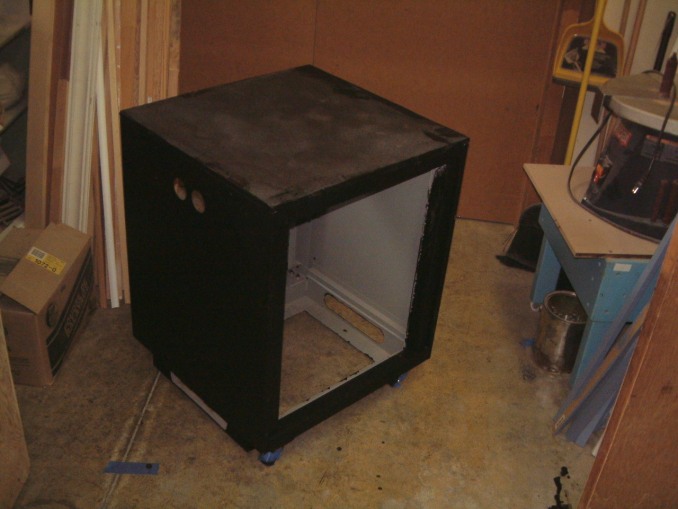 Here is is with the
flat black finish. I will have to wait until it is much warmer; then I can take
and lower the cabinet to the ground. I'll lay something on the paving to
protect it; and then I can spray-on the final wrinkle finish.
Here is is with the
flat black finish. I will have to wait until it is much warmer; then I can take
and lower the cabinet to the ground. I'll lay something on the paving to
protect it; and then I can spray-on the final wrinkle finish.
I'll eventually move it to the rear of the media room, placing it on the east wall and leaving plenty of space for the chairs. As the power amplifiers for the sub-woofers are under the raised platform in the tank room; heat wont be a problem.
 The final location,
up on the sub-woofer housing at the rear of the media room. Becauce the crackle
finish isn't hard, some areas seem brigter than others. We had to move it up to
the shipping door after it dried for two hours. Then, move it to the linal location
near the front of the offices. Then, though two doors and up almost two feet.
It barely fit (as you can see). The power amplifier for the left and
right front speakers, will fit in the lower location. There is room for the two
left ambience power amplifiers as well as the two right ambience power
amplifiers. The center channel power amplifier is in the center of the two
other power amplifiers (where else?)
The final location,
up on the sub-woofer housing at the rear of the media room. Becauce the crackle
finish isn't hard, some areas seem brigter than others. We had to move it up to
the shipping door after it dried for two hours. Then, move it to the linal location
near the front of the offices. Then, though two doors and up almost two feet.
It barely fit (as you can see). The power amplifier for the left and
right front speakers, will fit in the lower location. There is room for the two
left ambience power amplifiers as well as the two right ambience power
amplifiers. The center channel power amplifier is in the center of the two
other power amplifiers (where else?)
At the very near the bottom will
be the high-current phase reversing switches (above the top of the power
amplifier for the left and right front channels) will be the phase
switching. At the very top will be all the level controls for the power
ampliers\. (the relay rack had to be reveresed-side to side because one side at
the rear wasn't painted all the way to the bottom of the recess.
The crackle finish was better when it was swapped.
May 28th, 2008
After the Relay Rack Cabinet was completed, I was faced with some rough edges (sharp as hell). I have several rolls of trim (used for protecting sharp edges), that was ideal. Well, it was just the thing; now where did I stash it? I have to admit that I purcased it sometime in 1989 from Spae-Naur in Kitchener, Ontario. I began to use it as protective molding on things like the Flight Simulators, windshields, as well as metal cabinets. It took me several days to find where I put it away for safe keeping!
The black will protect people from "jaggie attacks". However, I had a power nibbler that worked in 1989. Golly, I remember that somebody dropped it, on the concrete shearing off the business end! I bought a replacement part; but somone cleaned up dumping a $275.00 tool, leaving the replacement behind!
Not to worry, Campbell and Hausfeld make an inexpensive pneumatic tool, Home Depot lists it. Not so easy. The expert 'associate' is Chinese; insisting that there isn't any tool, and attempts to sell me a 24" inch long sheet metal shear. In the process he manages to mispace the print-out!
the next day, braving the winds, I take a fresh print to the Home Depot store, and am able to convince an older person to go to the Campbell and Hausfeld web-site and locate the Nibbler. Armed with the SKU #, it is ordered from Campbell and Hausfeld, who are 14 Km from the store. Hopefully it won't be stolen!
With it, I can trim off the unneeded 16 gauge metal from the several holes, leading straight edges that I can cover with the trim.
I have to purchase some heavy-duty plugs tor the power amplifier output, I still have 25" of 8 gauge twin-cable as well as the required connectors. These will connect to the left and right front speakers.
June 1st, 2008
Woops, the RR case had an open bottom. If I used the compressed-air-nibbler on the 16 gauge steel cabinet, all the clippings would fall inside the cabinet. Even with a magnet it could take me several hours to clean up the mess.
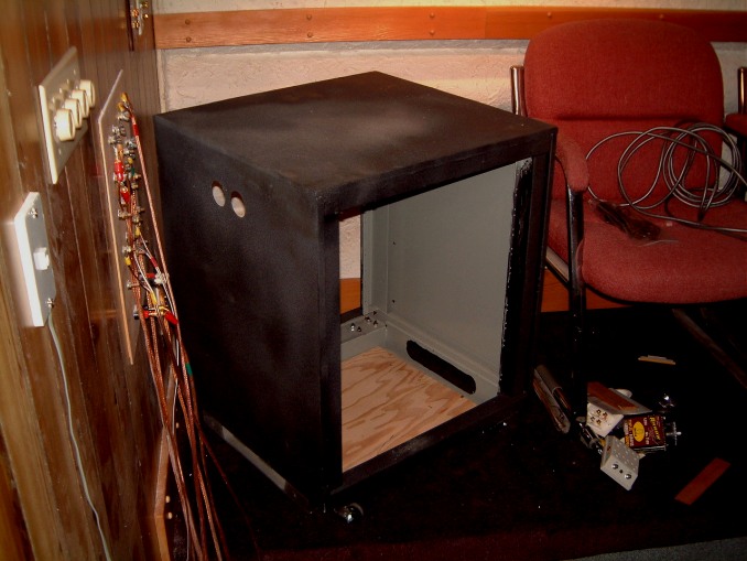 Here is the cabinet
with a plywood bottom glued in place.
Here is the cabinet
with a plywood bottom glued in place.
June 11th,2008
There always seems to be some unfished buisness that can hit you unawares! Late last fall we connected a insulated tube (6") to the media room to provide more ventilationas well as heating/cooling.With the double door shut it was very qiiet. We had an incident in 1975, when we were making speakers. When I was out, near 3:30 PM, a salesman called on us, as he wanted to audition some speakers. As nobody told me about his arrival, when the staff departed at 5:30 PM, I had to work late that evening. The last task that day was to test a new pair of monitors. So to say that I was startled when I opened the double door to the dimmed lighting, and found him sound asleep (genltly snoring) was a bit much. He was happy as he hadn't had so deep a rest for several weeks. However when he was told that it was 9:20 PM, he said that his wife would not be happy as he had promised her that he would be home at 6:30 PM at the latest. I had to let him out; and we never saw him again. He had left his card; so I was able to call him back. He begged me that if anybody called, I was to say that he had to visit a prospective client for a possible $12,000 sale.
It seemed to be very cold, probably because the concrete block wall between unit two and unit three left a one inch gap along 45% of the wall. When we first moved in (1880) unit two was occupied by Oak Ridges Stair and Railing Company and the migration of sawdust was terrible. We agreed to stuff the gap with fiberglass with a thin coat of silicone on the side of unit two. It was OK until 2004 when DecoraWall moved out. In the process of cleaning-out their unit the removed the thin layer of insulation. The first inkling we had of the gap was when we were invaded by sparrows that flew in from the open roll-up door loading dock door.
Well, it was OK for a while; we left some upper windows open (these had heavy screen mesh over them). But this summer it was very hot and humid. The solution seemed to be a high velocity exhaust fan located up on the mezzine where the vent was located. We cut out a 8" x 8" opening in the 3/8th Gyprock wall that allowed access to the water-line valve for the tap on the south side of the building.
 We used a
spring-loaded cover to mask the valve. Next to it, I installed a switch for the
exhaust fan with a pilot light that would indicate that there was power on the
fan. I got a 2 foot x 2 foot piece of medium-density board. I mounted an
electrical box on the the lower left corner of the 2 foot x two foot sheet so
that I could plug in the fan to a duplex receptacle. The power was connected
though a compresion-sealing-gland to a 30 foot length of yellow
Neoprene-covered 8 gauge cable with a standard 3-conductor cable that
plugged into a duplex receptacle bounted under the plants ceiling. This way, I
can move the fan easily if I need to use it somewhere else.
We used a
spring-loaded cover to mask the valve. Next to it, I installed a switch for the
exhaust fan with a pilot light that would indicate that there was power on the
fan. I got a 2 foot x 2 foot piece of medium-density board. I mounted an
electrical box on the the lower left corner of the 2 foot x two foot sheet so
that I could plug in the fan to a duplex receptacle. The power was connected
though a compresion-sealing-gland to a 30 foot length of yellow
Neoprene-covered 8 gauge cable with a standard 3-conductor cable that
plugged into a duplex receptacle bounted under the plants ceiling. This way, I
can move the fan easily if I need to use it somewhere else.
As I stated the upper housing was fabricated of two pieces of medium-density 3/8th inch board. These were spaced apart by 10 inch 5/6 th G1S plywood fitted in the top and to each side, leaving the bottom open for the exhaust duct.
Here is part of the upper exhaust box, in the shot the fan is on the top
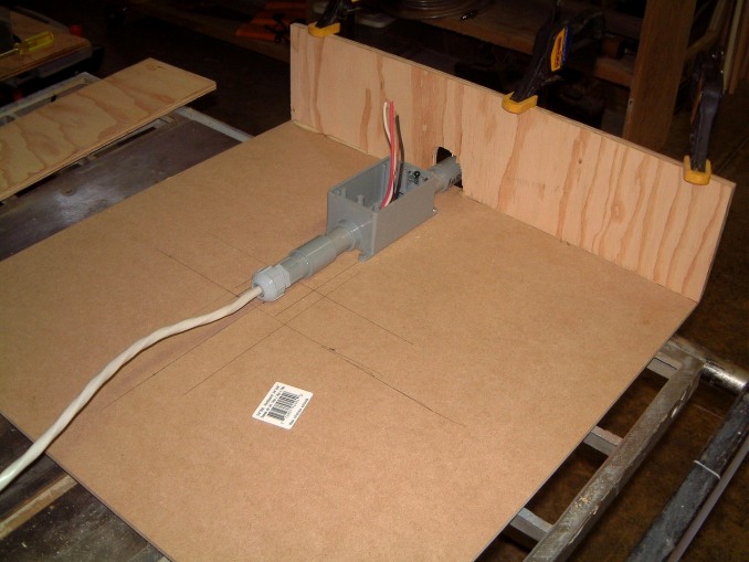
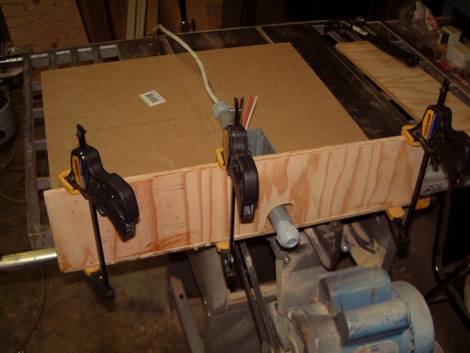 The top is
being assembled using glue. The plastic wiring box has been screwed to the 2' x
2' rear panel. The electrical cord will be placed in the strain relief in the
foreground. The top is 7/16 th plywood as are the sides.
The top is
being assembled using glue. The plastic wiring box has been screwed to the 2' x
2' rear panel. The electrical cord will be placed in the strain relief in the
foreground. The top is 7/16 th plywood as are the sides.
I used a portable exhaust fan, sealing it with two inches if urethane foam. The adhesive was applied only to the medium-density board as the suction was stong enough to prevent from moving. A couple of clips were enough. Inside the media room the sound of the fan is unnoticeable. If it wasn't for the red pilot light on the switch plate cover, there wouldn't be a clue.
The exhaust fan is mounted on four pieces 2" x 2" glued to the base of the housing. The base is attatched to a strip of felt. There are several wood screws holding to the srean-board floor. If needed, it can be removed easily as there is several feet of BX cable free so that the duct insulation can be changed by extracting it from the top. A first we lined it with fibreglass, then a thick felt. There is a better type of felt that might be available that has less air resistance; we will be able to use it when it is certified as safe.
The housing took longer than I expected. Here are four more shots.

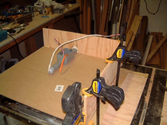
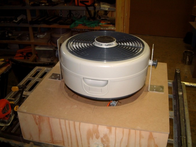
 In the last two shots,
the fan is on the top.
In the last two shots,
the fan is on the top.
I had to take some time to clean up the small pieces of steel that the nibbler produced. Thank heavens I had a strong ceramic magnet that was able to pick up the waste.
Thank heavens that it's been too hot and humid up on the mezzanine to work, there are several days left until it has to be done. I have to move four IM-10's that weigh 75 over pounds each. Only then can I screw-down the pieces of 1" x 2" that form the rim of the exhaust fan.
July 6th, 2008
Simple errors are sometimes hard to correct. The ninety degree wide rim at the bottom of the upper exhaust-fan was seven degrees off (too little). In desperation I cut a narrow slot half way through the medium density material and dribbled some water into the slot.Two hours later I clamped the slotted part into a 92 degree jig; letting it dry overnight. In the meantime I'd cut down the aluminum fan bracket. Then I re-mounted the shortened brackets. After the sparing use of some Bondo (tm) , I masked and sprayed the housing with a textured paint (effectively hiding some small errors). I glued on the urethane foam to seal the exhaust fan. With the lower wiring box ready to connect, I finally mounted it to the lower duct. Unfortunatly I had to move five (heavy) Interface units - XIM II''s to screw down the upper exhaust fan housing to the floor.
When I finally tied-up the power cord so that it had power, the relief was as much for the completion of the months work as the quiet criculation of cold air though the media room! I was finally able to clean-up the small amount of scrap; vaccumming up the floor once more. Biting the bullet, I found the cuved needles and completed the stitching on the edges of the carpet on the elevated rear part.
Now I had to move the power amplifiers into the Relay Rack. The lower power amplifier (for the left and right front channels) was simple as I'd made up the connections to the distribution panel at the rear of the room. The low frequency - cutoff was allready mounted at the front (hidden by the two speaker cabinets).
The sub-woofer power amplifiers were located next door under the tank-room platform. I had to make the supports for the rest of of the smaller power amplifiers that were for the center speaker (front), the four ambience speakers at the sides and the two speakers at the rear. Phasing the center speakers was easy; I simply switched the two banana plugs and changed the red and black covers. The side ambience speakers were set-up the same way. As the power amplifiers had their own level controls it was easy-enough. (I used the tape inputs for all the side ambience and was able to fiddle a bit with the bass and treble settings to balance them out.
The last thing I have yet to do, was to adjust the settings on the Audigy. It may be fortunate that most of varuous adlustments should work.
July 18th, 2008
Back to the media room once more. The top on the old Ikea cabinet is too smalll to be used for a keyboard, a mouse, a monitor, a computer, an external high-capacity hard drive plus a joystick.
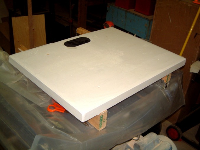
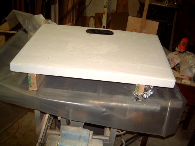 The top
was 1/2 inch scrap plywood with a lot of sanding and filling. The edges were
reinforced with 1" x 2" birch with a wide recess for the top; the
actual exposure for the trim was about a quarter of an inch. A black plastic
fitting makes a neat trim for all the cables.
The top
was 1/2 inch scrap plywood with a lot of sanding and filling. The edges were
reinforced with 1" x 2" birch with a wide recess for the top; the
actual exposure for the trim was about a quarter of an inch. A black plastic
fitting makes a neat trim for all the cables.
.
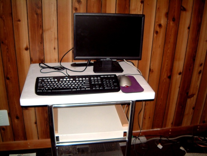 The finshed Ikea stand is allmost complete. I tried it to gauge the available
space. The Win XP-Pro computer hasn't been moved yet. I must ensure that the
Samsung S-Video to DVD transfer system will have enough ventilation. I
have to place an S-video player/recoder underneath the Samsung unit.
The finshed Ikea stand is allmost complete. I tried it to gauge the available
space. The Win XP-Pro computer hasn't been moved yet. I must ensure that the
Samsung S-Video to DVD transfer system will have enough ventilation. I
have to place an S-video player/recoder underneath the Samsung unit.
July 19th, 2008
And in an addition to the exhaust fan - I
forgot its switch!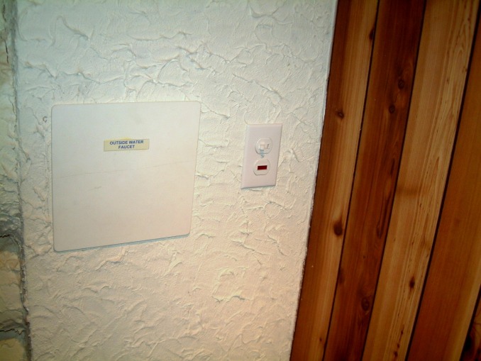 When its not raining behind the plant, I can finally spray the exhaust fan
cabinet. This will be a releif as its far too warm and humid to work
there for over an hour or two!
When its not raining behind the plant, I can finally spray the exhaust fan
cabinet. This will be a releif as its far too warm and humid to work
there for over an hour or two!
August 20th, 2008
An unavoidable delay happened as more alterations in the Media Room were due, it took much longer to tranfer the older MS XX Pro (build 3) computer. First the mouse was dead. Three mice later it worked. Then the Cat 5e connection (port 8) failed. It took the better part of a week to check out the cable using a large loop for testing. Somewhere I had socked away a 200 ft cable. I found it and was finally able to verify the integrity od the cable. There was a short length of blue Cat 5e cable from the jack to the D-link broadband VNP Router. Jack 8 couldn't be unplugged.
As I said only the Belkin Gigabit Router has to be configured. Most of my computers are not very high speed so Cat 5e is OK on these. Only the newer and faster computer needs the Cat 6e transfer speed. As this router has an attenna (for security reasons) have to disable these for some computes on our network) and use another wireless router for the less secure computers.
Here is the final untanglement of the wires under the working are where the web
updates happen.
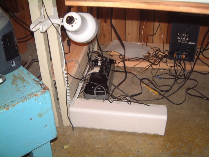 Then the change to the Cat 6e cabling
had to be completed.
Then the change to the Cat 6e cabling
had to be completed.
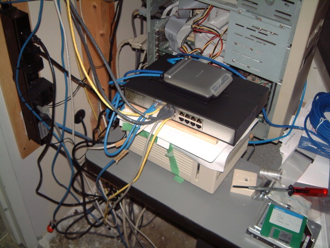
This shows
the smaller gigabit router with the sixteen connection gigabit switch. Both of
these operate using much lower power. Both remain cool.
There seems to be some confusion about gigsbit routers and switches. Remember that the connecion speed using a DSL connection is limited to a certain speed, the computers themselves on a gigabite speed switch are limited only by the speed of the indivdual computers themselves. Obviously the speed of the DSL is the ultimate barrier. However, computers on a gigabit switch are limited only by those computers that are essential to the overall shared computing system. Therefore when dealing with such items as complex graphics that are needed for HDTV editing in real time, can be limited by any transitional item such as merging two frames. That is why extra allowance must be in place if the merge is very complev. The slowest thing is the transition time needed for seamlessly merging graphics with HDTV.
That is why the Farouga technology is essential to these types of effects.
The curse is the immence amount of bandwith used by FaceBook and similar programs. Any new device that is a 'bandwidth hog' and will eventually result in the inevitable increase in cost. This is similar to the prices of Gasoline. Even now, it has affected the cost of the Apple G that uses more bandwith and causes overloading of the network servers.
The latest addition to the Barco 801s, is the HDfury2 Kit and the 3x1 Smart HDMI Switch. These are shipped directly from Taiwan, both add up to about $300.
Port3 as RGBHV Input a nine pin connector next to the power connection on the BARCO 801s. The ** indicates a possible exeption. On some Model 801s projectors these connection were removed to aid in cooling and to save current draw.
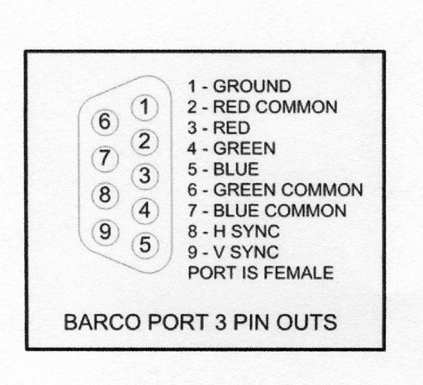 This diagram shows
the connections to the BARCO 801s.
This diagram shows
the connections to the BARCO 801s.
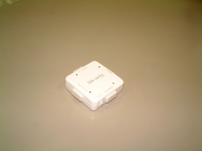 This (small) three
input selector switch ( with another device, connects to Port 3.
This (small) three
input selector switch ( with another device, connects to Port 3.
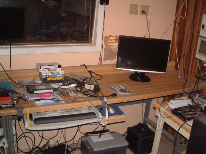
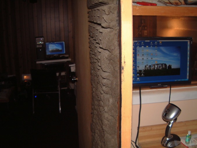 Linked monitors, one in media room, second in HDTV lab.
This makes it easire to see the results of editing before using the Barco.
Linked monitors, one in media room, second in HDTV lab.
This makes it easire to see the results of editing before using the Barco.
September 24th, 2008
I am still waiting for a component that was supposed to be shipped about the tenth of September. The rest of the new HDTV Win XT Pro was completed over two months ago. Now the needed portitoning has been finished, AGT 8 installed, and the Pinnacle software set up. However I still have to have a different type of HDTV output connector installed. The current output connector is OK for a 24 inch HDTV monitor but not a seperate output.
Dammit, still one more problem at home. I installed Norton four years ago on a Win 2000 machine. There wasn't any problems with the renewals in our plant. So I took it home, and allowed the Norton Stuff to continue until I had only three weeks left. Then because our IP address is different Norton can not be coaxed to alter the new address. No problem. I removed all of Norton except for the firewall. Then I attempted to ldownload AGT 8, disabling the firewall for five miutes. Now AGT times out before the transaction starts. After thrty four-attempts over two hours, I renabled the firewall and quit!
The only thing that comes to mind, is that Norton will not allow anything new to be used. Now, a day later I have to admit that when it was transferred to a CD, I was able to istall it. I was able to get Norton Uninsaller from my technical advisor, and it worked!
The movie cameras I am using range from a 1980 S-Video unit (no photo), a old Sony.
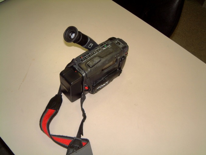 This is a later camera,
much more portable. It even has image stabilization.
This is a later camera,
much more portable. It even has image stabilization.

Finally I was able to trade in the s-video unit to an person that had the older
type of lithium battery explode. The company replaced it, but he was quite
anxious to buy my older camera
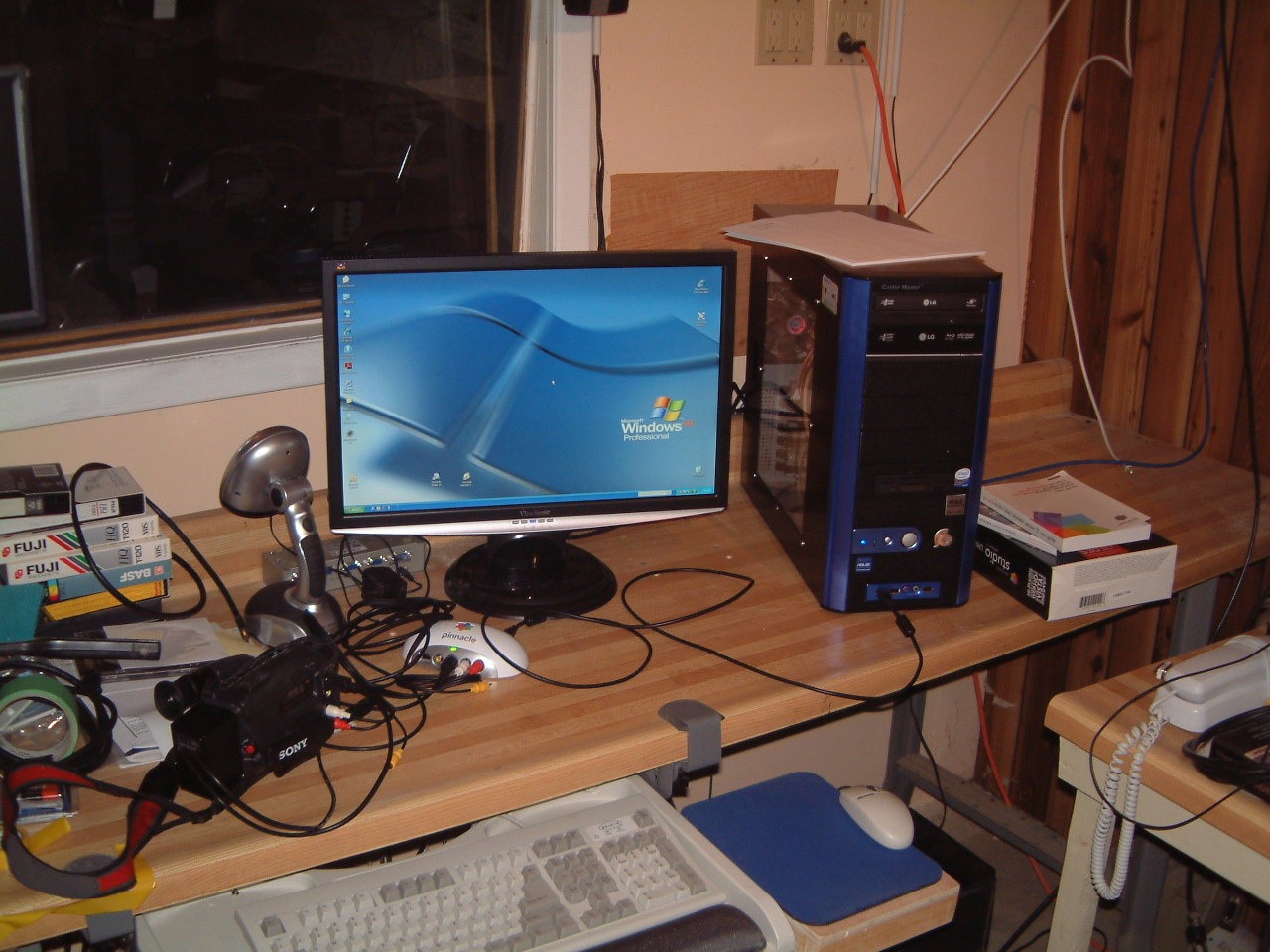 This is the new computer for editing and producing movies. It has HDTV as well
as a choice of either DVD or Blueray formats. I have a minor problem in that
the Pinnacle input box is properly instaled the front input receptacle doesn't
recognise the camera.
This is the new computer for editing and producing movies. It has HDTV as well
as a choice of either DVD or Blueray formats. I have a minor problem in that
the Pinnacle input box is properly instaled the front input receptacle doesn't
recognise the camera.
September 29th,
2008
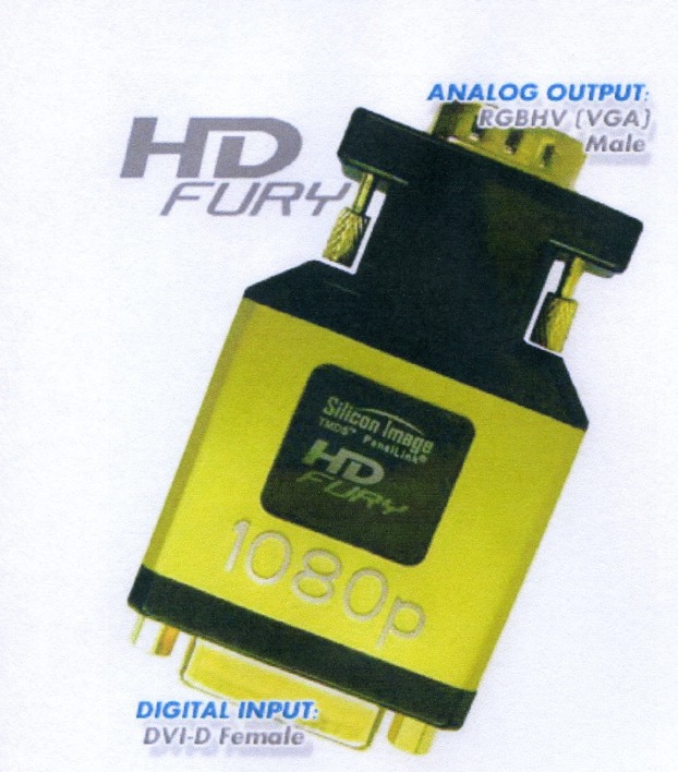 The connector has an HD
Fury chip built in. This convertsthe signal to HDTV format. This is what I am
still expecting to be shipped in the middle of the month. We will see!
The connector has an HD
Fury chip built in. This convertsthe signal to HDTV format. This is what I am
still expecting to be shipped in the middle of the month. We will see!
October 7th,
2008
This is the third attempt to make the Netscape 4.79 editor function.
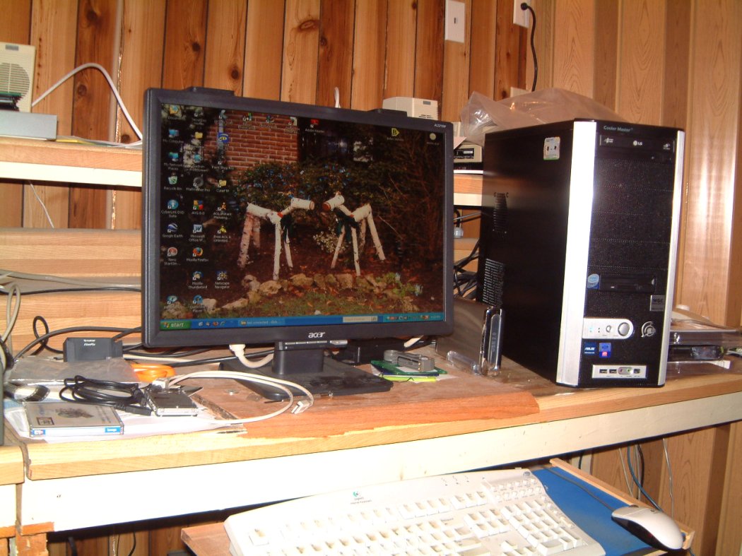
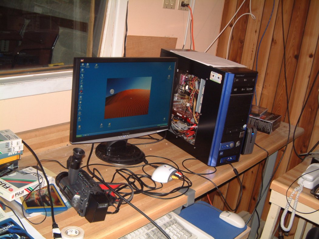 This
new attempt might work
This
new attempt might work
November 15th, 2008
I found a way to upload a different program by by-passing Cute FTP.
It works!
To continue, I am way behind in the new information I have re: The Pinnacle 12 STUDIO Ultimate.
It's a bit tricky to use. The main thing to allow for is the rendering time
necessary for transitions
and fades The program allows
correction of saturation, hue, contrast and other essentials needed. The
titeler allows for roll-ups, streeming characters any where on the title. The
amount of contro in the sound track and the narration is great.
November 22th, 2008
Correcting the error was simple, all I had to do was go to "Permissions" to authorize the transfer from the Public folder in my computer, to the Public file that to which I was uploading.
January 11th,
2009
A new year comes with too #%*^& much snow, freezing rain, black ice, sub zero temperatures and the usual speeding drivers who think that the fastest way to negotiate heavy traffic is to race ahead of other vehicles in a useless attempt to get to the next red light. As the old saying goes, high speed highways are the fastest way to arrive at the next accident! I am still amazed at the number of otherwise responsible people who get into a vehicle and shut down their brain before starting the engine! I see them every day walking around the malls, cell phone in hand, totally unaware that they are walking into other people. It never seems to stop; they leave the malls, still listening to their cell phone, get into their car, still listening to their cell phone, start the car, still listening to their cell phone, drive out of the parking slot, still listening to their cell phone, and collide with another idiot, both of whom are still listening to their cell phones!
It's interesting to see them raving, at each other, still listening to their cell phones.
What is another hazard is pedestrians, well shielded frpm the weather with heavy parkas, still listening to their cell phone or mp3 players or, even worse, attempting to text message, with numb fingers!
February 14th, 2009
Another week, however's it's actually above zero Celcius and the snow is starting to melt and with it we are getting three foot long ( x 11 ins. x 13 ins) chunks of ice dropping 26 feet down into our back yard at home. Thank God, I anticipated this and construced a concrete block planter behind our home. It's three blocks high with a cast concrete cap that's strong enough to withstand the chunks of ice that fall. We planted Berkman cedar along the rear wall and six feet at right angled parallel to the jutting wall of the next house. This way, part of the fall is cushioned by the cedars. We have a table and chairs with the tempered glass table well clear of any falling ice. At the other side of the patio door, we have a window well that has both a heavy 12 Gauge screen + a slanted plasic cover with a 10 inch over hang on the 7/8 th' plywood (with roll roofing) that protects the barbecue.
The sole exposed, item is the Gas Meter for our home. We've had three heavy winters with five foot snowbanks on each side of our driveway. So every time it snows (usually about a foot and a half over 24 to 36 hours per day. with a two day breather in between!
As this is the time when all the MSDS's have to be updated four times 7 languages for the web + three times three printed MSDS's.
And at the last possible moment there always some recently added thing for all of them.
As I noted in early November, the Win 98 computer was hacked; I was using AVG 7+ at the time and some $%*&$ attempted to disable the firewall. I was able to fix the damage and changed the passwords. However six days later he located another back door and I had to change to Win XP Pro, 3rd. I took me ten days to find Netscape 4.7 + that I could use with XP Pro.
Thats why I have been remiss in updatind the Room Construction part of the dayton-wright.com web site.
March 11th, 2009
Well I'm allmost caught up now. We've been informed that the group that was going to manufature The Dayton Wright Esl's in Michigan has decided (after 4 years) to defauut on their committment, leaving us stuck with 90% of the stock still stored in Richmond Hill (We've been paying the cost of storage for three years at a total cost of $3000 per month. Our agreement was that we would pay the cost of storage for one year - and might extend it a month at a time, providing we saw some effort on their part to start the process of trucking the stock to Grand Rapids, Michigan. So far they have trucked our tools and dies - on a lease basis - and taken most of the perforated metal electrode stock. One condition of the contract was that they must strip the lead plating (the ternplate is steel plated with lead). (We had shiped Leigh all of our stator electrodes with nickel plating and we were horrified to find out that Leigh deemed to use tern plated steel - it's cheaper).
We loaned them $4700 of custom Hammind transformers as well. Now we face the legal cost as well as the cost of trucking it back from their plant. Their only excuse seems to be that they spent too much money on purchasing heavy used tooling and did not seem to realise that they did not have the time, talent or money to go off on a very expensive undertaking. We told Greg several times that he had to produce about two to ten pair of the ESL's. Only then could he estmate the cost of production. We could delay a reasonable period until he had even a tentative cost estimate. We pressed him (gently), but all we ever received was reasons for delays and proposals for re-design of the ESL's. We said the agreement was based on manufaturing two dozen pair of ESL's to our design as we had a hell-of-a-lot of production experience!. Within several months all we recived were re-design proposals. We reminded Greg in advance, before he was about to pick up any material that he would have enough parts to run about 5 to 10 pairs of the existing design and then he'd be better able to work out any manufacturing problems. Then, to keep it simple as possible until he knew all the steps in planning even prototype runs.
We had e-mailed Greg a proposed contract. Then told us that his e-mail was screwed up; and gave us a new e-mail address. We e-mail'd Greg the proposed contract, e-mailing our lawyer the same proposed contract for vetting. More delays ensued.
But we never seeme'd to get ahead. We had to start to dissasemble wooden fixtures in the rear of our plant and make arrangements for their storage. We kept telling Greg that we were pressed to accept shipments of materials and stock for our other business's at our plant. By 2007 we had run out of room and could not operate the profitable parts of our buisness as we could not operate in the chaotic conditions brought about by lack of organized storage.
Then Greg told us that we had to scrap half of the wooden parts used for the ESL's as the cost of trucking was too expensive. We told him that I did not have the time or the strength to load four fouty five foot trailer loads, and did he have any suggestions? (He had told us that he could rent a fork lift truck to move some of the stock out of our plant. I replied, "Fine, set a date and we'll help you."
We never got a reply. By this time I was a bit curt with Greg, pointing out that he never seemed to follow through with my replies.
Then, he informed me that he was broke. I asked him by e-mail (I do not trust phone calls), to at least send me a fax with a cogent proposal on what we could could do. We never recived an answer.
Now I am faced with at least $37,000 of storage costs and well over $19,400 of lost tooling!
April 14th,
2010.
After several months, I was able to perform some more updates. As sombody may realize, last fall Microsoft and Google were hacked by experts. This seemed to follow the attack several years ago when Win 98 suffered damage.
Nobody seemed to know why these earlier attacks took place? Was it simple vandalism or was it a well planned concerted attack on major URL's?
In Toronto and in Waterloo, both in Ontario; a group of experts pooled their resources. They knew where it seemed to originate. One faction attempted to link it to China's Olympic Games. However that seemed presumptuous. The majority could not be certain as the attack was so sudden and too widespread to be easily located to even a well-planned infection that could be triggered by any simple event.
It seemed two selective in it's methodology; so even the experts were unable to locate a simple 'linkage' to any well planed nexus or distribution or insertion point. However it was suddenly so widespread that an unusual number of operating systems were infected.
More to arrive!
October 24th, 2010
Well
after a hard drive on my computer was fried by a energy surge, I am able to
edit these entries. There are nomerous photos to add.
I had to repace my old table saw
as it didn't have a belt guard or cover. So I could not legally us it. We boght
a new saw from BusyBee tools, it was properly shielded and had a good
recovery system for the sawdust. This connected to a vaccum system that I
had insalled when we first began to make wooden cabinets in 1996 in our factory
on Idustral Road in Ricmond Hill. We were taken over by Leigh Instruments in
Waterloo.
However we were able to purchase it back when Leigh Instruments got in to finacial trouble.
We had to form a new compay to take over the manufacture of Stabilant. Previously we licenced it to Sumiko in the west coast where it was marketed as 'Tweak'. Their sales were restricted to the Audio Industry. But when the patent was granted we forned a new Corporation; D. W. Electrochemicals ltd.
We completely renovated the old plant in Richmond Hill installing careting in all the offices repainting all the walls and bulding new furniture as needed.
I made a new Invocing and Purching system that complied with the Yk2 ruling. (All of our customers seemed to have completly different legal forms for use to fill out and sign).
In late
January of 2011 our first hard drive in our main computer was damage by an
unexpected power surge; we have a seprate UPS for each computer' It's
taken os this long to get our system patially running!


To continue, I have to jump back several
years. I realise that the following doesn't fit in, however I do not want to
re-edit this inclusion!
March 28th, 2003.
However, before I was finally able to mount any speaker, Inade the mistake of attempting to use a drill-mounted sanding drum to smooth the holes in the sub-woofer panels. Not only was it difficult to accomplish, it was a mess when I finally created a smooth-sided hole; about an sixteenth-of-an inch oversize. Suffering from mild frustration I decided to buy a vertically oscillating drum sander. This was much easier.
 As an aside,
I had to take an old castered frame that had an open top, mount a new set of
castors on the legs, then screw a medium-density fibreboard panel on the top.
This gave me the support for the drum sander that I could move about the
carpentry shop. It has a sawdust vent at the rear, a most inconvenient
location. At first glance I thought I migt have to put a bulkhead fitting on
the top of the base, using a hose to connect to the sander. Then, I measured
the opening for the hose (difficult to do when it's already mounted on a
stand), and run another shorter hose into the bin or a container under the
stand. When I measured the opening for the hose, it was about 2
1/2". Scrap that. I had some hose of the correct diameter that could be
used with a wet/dry vacuum ckeaner.
As an aside,
I had to take an old castered frame that had an open top, mount a new set of
castors on the legs, then screw a medium-density fibreboard panel on the top.
This gave me the support for the drum sander that I could move about the
carpentry shop. It has a sawdust vent at the rear, a most inconvenient
location. At first glance I thought I migt have to put a bulkhead fitting on
the top of the base, using a hose to connect to the sander. Then, I measured
the opening for the hose (difficult to do when it's already mounted on a
stand), and run another shorter hose into the bin or a container under the
stand. When I measured the opening for the hose, it was about 2
1/2". Scrap that. I had some hose of the correct diameter that could be
used with a wet/dry vacuum ckeaner.
But some things cannot be accomplished when you don't have the time. I had been postponing the connections of the speaker because of the wiring for the Flight Simulator. I have to jump back and forth all the time; parts seem to have a mind of their own. I keep telling myself that by this time in my life, I should be able to juggle ten disparate tasks without being driven nuts. Perhaps, I'm just kidding myself.
September 11 th, 2003.
The support for the rear platform was designed for ten 2" x 4" frames. But fitting ten frames did not leave enough room for four ten inch sub-woofers! So much for the ten frames, I finally settled on five, with extra supports and added bridging across the rear of the platform.
By mounting the sub-woofers on the outside of the "cabinet" it is much easier to make the parallel connections. As the sub-woofers are eight ohms each, the parallel connections result in a four ohm load. By connecting in parallel, any "back EMF" does not disturb the "shared" load.
I have decided to cut away the carpeting under the platform. I will cement 3/8 " filler strips directly onto the concrete floor. This allows me to use a solid back to the platform as well as using a solid partition and solid ends. The tilted baffles will be glued to horizontally run moldings on the fillers and I can use a wider (vertical) filler right up against the platform floor, with the addition of a 2" x 2" reinforcing piece that can be screwed-in from above.I should have taken a lot more time with the platform; perhaps then, I would have realised earlier, that it made a perfect location for the sub-woofers. I have to confess that I had spent too much time in planning the "extraction" of Max's console from the rear of the sound/media room to consider that the platform as a sub-woofer enclosure.
I just discovered that Lepage now produces "No more nails", a (Multi-purpose/Multi-usage" adhesive. I still used a couple of one and one-eight inch drywall in pre-drilled holes (pre-beveled too), just in case! The "no-more-nails" slogan bugged me until I read the disclamer that it shouldn't be used on non-porus surfaces. Reach for the hardened steel dry-wall screws once more.
From
the photo, you can see the inclined sub-woofer panel. Sorry about the stippled
gray finish, but a long time ago, I settled on what was, at that time, a finish
that was made for automobile trunk compartments. It is durable, and best of
all, is very good at hiding blemishes!
The rear of the platform will be "sealed" by inserts behind the rear of the 2" x 4" vertical pieces. A horizontal piece of 2" x 4" will be place by the use of right angle brackets between the verticals. The liberal use of foam can be used to seal any gaps. Then a twelve inch wide horizontal filler will run the entire length of the platform. (It will be in two pieces).
Obviously, the surface of the platform will be divided on the centerline of the 2" x 4"'s.
I have a nineteen inch relay rack, (on castors) to support the amplifiers. The rack is only forty eight inches high (including castors). If I make the elevated platform thirty nine inches in width, I can seat four more people in the rear.
For more hints on this type of thing, look at installation.
September 19 th, 2003.
In my quest for additional stuff that I can use with the Barco 808s - I was able to locate a Faruodja VP400 line quadrupler. This is designed for rack mounting and it is the 'professional' model of the model VP401. This was used, for example, in 'Planet Hollywood'. and it is very compatable with the Barco.
![]()
![]()
I still have to remove the stickers from the front, but I'll have to make sure that it's OK. Then, I'll wait until I can mount it on the relay rack. The same relay rack will accomodate the Barco Switcher RCDVS (which handles several type of Video and Stereo audio) as well as the smaller Barco Video Switcher.
I have to admit it, I dislike over complications in system design, but often, the layout is influenced by what is available (and cheap). When everything is tested, and rack mounted, I will take photo's of the stuff and I'll attempt to explain how-in-hell it's supposed to work! (And IF I can make sense of the logic involved, I might supply a wiring diagram.
A year ago I purchased a Barco RCDVS-05 (standing for Remote Control Video/Data Selector). This allows several sources of video and audio to be selected. The output on this switcher allows for a five lead (RBG-Sync -etc) as well as the stereo audio. (it has a s-video as well as a normal video connector.
![]()
![]()
This will allow me to select the inputs to the Farouga line quadrupler. As this selection device will handle component video as well as s-video, I wil be able to use it with Laser Discs as well as either video tapes or s-video tapes. DVD's, will be run via the Audigy II card to read and convert, as needed, the audio to Dolby 6.1 ex. The Faruodja VP400 line quadrupler, is ideal for converting S-Video's 256 lines to1024 line output or to convert normal TV signals to 1024 lines. The Barco uses Faruodja technology to, as needed, to double the scan. HDTV inputs, are handled in a pass-through method. The high frequencies can be 'peaked' to enhance the detail. I also have a Panasonic three sensor Professional Video camera that has an s-video output. The effect of passing its output signal through the Faruodja line quadrupler is amazing as it allows it to selectivly 'sharpen' images.
October 11 th, 2003.
I had a pleasant suprise this past Saturday. Three years ago, I bought a Sony three sensor professional Video Camera as well as its Video Control box, BUT, some other shopper 'snaffeled' the camera's power supply while I was checking out my bargains. I could not find it anywhere at TelAv.
Suprise. This year I saw the missing Power Supply and, as I remembered the last six digits pf the SKEW number as well as the camera number (#2), I was delighted when I found it. As I had over fifty feet of the cable that connects the Camera Control Unit to the Camera itself I hooked it up and found that everything worked. Now, I have to confess that I am an 'avid collector' of electronics - as long as I can get it to work. I know where another camera and control box is located (it is #1), but, it is also missing its power supply. I have found out the hard way - when you're dealing with Japanese Manufacturers you MUST know exactly what you are looking for. If you have the model and serial number sequence, generally, they might be able to locate it. As there are @*^#?W% products in their lists (with all sorts of classifications) even locating a power supply connector can be difficult. With the needed conector, it's possible to 'scratch build' a power supply that will meet the 'specs' of the origonal (the current parts design's) are generally better.
I decided to revert to a normal closed side relay rack as I needed the flat top to support a 17" monitor that will allow me to check the various input signals. I will still use castors on the relay-rack so that I will be able to hide (the always too long) BNC cables. The amount of short lengths of BNC cable I'll have to use is still is a worry!
A general apology is due to those people who use (as I used to do), a dial up connection to the internet. I know what it must be irksome to have to wait until a gif loads. We have been suffering (as many people who have come to rely on the internet). The number of new worms seems to be one the rise. (We use Symatic and Panda to entrap worms and virus' and have to update out firewall constantly.)
Good news,after spending three and a half years running Cat3e cable around our plant, in September 2006, we were finally able to switch to DSL
We now believe we have saved ten to twenty hours a week in updating all of our
computers. For example the Win XP Pro could take five hours to update some
security items, They generally had to be done after midnight so our dial-up
connection wouldn't be disconnrcted We often we would return after 8 AM only to
find that we had to re-connect to redo the update. We were aware that some
updates require re-booting the computer after some updates. Years ago we
installed large UPS's on every computer in our plant. We also have them at home
on the TV set, on every piece of electronic apparatus including computers. Even
with hagce capacity surge protectors we lost three TV sets before we switched o
the UPS's. At a typical cost of $160 per UPS, it's saved us over $1,200.

© 1980, 1990, 2004, 2006, 2007, 2009 - Wright Electroacoustics