
DAYTON WRIGHT
LIMITED
We are changing the formatting of this web-site. By double clicking on an image, the image will be enlarged to a high color JPG. Some if these additions are already in place. The rest will occur when we can find the time!
We seem to be always in need of something in order to complete a project. In this case we need several stackable computers to be used as 'clients'. They should be Pentium three's or four's with at least 128 Meg of DDR memory. We will install Windows 2000 on our own Western Digital 80 Gb hard drives. A CD-Rom is necessary. The stackable configuration is necessary in order to save space. The usual dimensions are:
Vertical - 1 3/4 inch
Horizontal width - 17 1/2 inch
Horizontal depth - 20 1/2 inch
In an ideal situation all of them should be made by the same firm. --- WW
Note: This was written about Windows 98. Things have clanged dramatically since that date.
We are now using WidevieW with five CRT montors and using Microsoft's flight simulator 2000.
Sometime when we can affoerd it, we will switch to 21 inch flat screen
monitors. This will be under the Sound/Media room planning.section.
Planning:
In nineteen hundred and sixty eight, we first began the planning needed to manufacture Electrostatic Loudspeakers. because of our experience with Wright St. George, we knew that securing start-up funding would be tough. We also realized, that the manufacturing of only ESL's, would make us extremely vulnerable to dealers not paying promptly. This would be worse if we began to ship to the U.S. market right away! In order to broaden the initial market base, we planned to offer two systems; one would be based on a companion power amplifier, the next one would use step-up transformers.
As we anticipated the need for a simple preamplifier for the dealers to use when they were demonstrating our ESL's, we started to design such a unit that could form the basis for training technicians.
When we were satisfied with the first year's production of our ESL's, we would begin a limited production run of preamplifiers. These would also enable us to spread the risk of dealers who could make us wait for several months until they paid. In order to ensure that there would be no excuse for non-payment, we established tight Quality Assurance standards. This seemed to work well until we found that some U.S. based manufacturers were not really inclined to meet our QC standards. Ths was especially true of High Voltage Power Supplies. Based on our research, we were very suspicious of the use of PCB's in insulating oils! We made it a condition of acceptance of our orders, that a manufacturer must certify that there were no PCB's in any High Voltage Power Supply before we would confirm the P.O.
To our dismay, even though their certification had been sent to us, one manufacturer used PCB's in part of his run. As the 'cans' for this part of the run were smaller, were suspicious. By this time we had locates a company that could test for PCB's. Following their instructions, we had unsoldered the filler hole and had extracted less than a CC of the oil from each of the first twenty-five pieces of the shipment. We were shocked to find when a gas chromatographic analysis was performed, eleven of the these had used PCB's in the oil. We immediately contacted the Mfg. who claimed that new staff were responsible!
We quarantined the shipment and immediately began an accelerated life-test (well within our specs). Within four months, twenty seven had failed! The failure rate was 90% on the non PCB supplies but was still about 50% on the rest. It was evident to us, that even the use of PCB's didn't work!
This is typical of what we faced during the first years of the business.
Staff training was very important, equally as important as Quality Control. We pioneered the modular design approach, and were the first company in Canada to employ co-ordinate dimensioning in short-run production!
When I started to work in Boston (1962), co-ordinate dimensioning was in its heyday. CAD/CAM was first being used experimentally. Cost control and planning were being embraced. Value analysis was the great hope in designing.
A hell of a lot has happened in that period. Down sizing is now endemic. The company politicians (suits) have placed profit ahead of ethics, and in the process have taken over from the competent people in the name of multinationalism.
(long sigh)
The Move and Stock Control:
Our plant has been constantly in an updating process, since nineteen eighty when we moved to the present address. We started with a S-100 computer, writing C-Basic software to sort-out the inventory we acquired from Leigh Industries when we bought the company back.
We had to set-up an inventory control system which allowed us to track everything! This included work in progress. We established a new system, which was based, in part, by rationalizing Leigh's system. We had a an inventory control system based on punch card's. Each item in the plant was assigned a card; these cards were updated on a bi-monthly basis. Every time we went out to acqire any item (new items were always assigned a new card and it was part of my job to classify each new item and make sure that a proper item card was created.
This was easy to do once the staff got aquained with the system. As a consequence, we almost never ran out!
We found some glaring gaps. The most obvious to us, was the fact that Leigh had 'misplaced' over 500 pieces of pre-cut sides for the XG-10's! this happened, we surmised, when Leigh was transferring come stock, from their other plant. At the same time, they were rearranging their Weber Street plant. Their carpentry crew built a new partition without realizing that the stacks of pre-cut sides, were blocking the other door into the stock area. You see, that door opened inward. The new partition did not have a door!
(But whoever When the
stock couldn't be located, Leigh simply ordered replacement parts)!
They sent us an especially
nasy letter from their lawers 'saying in essence that they had very deep
pockets and they could bankrupt us. More and more BS!
By this time, we needed more than a simple speaker testing set-up like Leigh had been attempting to use. Their set-up was a six-foot by seven-foot well padded room that they had destroyed before we had finished moving.
After the move, the Dayton Wright Group Group Ltd., was short on funds. I decided that I would pay must of the new plant costs by using my own companies funds, billed to Wright Electroacoustics. This gave me some extra leeway; so I decided to cap it at $29,000. I had saved over that amount by not purchasing new tools whenever I was able to get an good price on someting essential to production. A good example of this was when I was able to get an good small rubber mill for $2250 Canadian. It was very heavy and it took five people to move it into our plant at 97 Newkirk Road North. We were able to install it in the machine shop area adjacent to the small milling machine and metal lathe. We got it in Phoenix on a trip back from a trade show in Las Vegas.
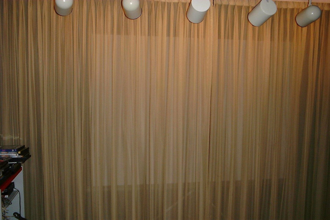
I had to install a room where I could listen to loud speakers. It needed
some sort of a 'masking scrim, where we could hide
the speakers; by making the area where
I could set up the (stereo) speakers. I decided to store them in an deadened
area adjacent to the listening area. I had constructed a portable
isolation tank with a removable cover. (I was able to get a US goverment
grant for $12,000 US) to cover it's construction. But the second $12,000
US payment never came. I had a phone number for the office. But
this line was dead and the operator took
a guess and told me that it was someplace in Maryland.
When I planned the....first named the 'Listening Room' as its first function was to be a small recording studio come serious audition room. Good planning was my first concern.
I had to reserved four to five feet on the listener's end to that would enable me to construct an elevated 'sound studio control room'! Which because of it's five foot verical displacement, would allow the room to be much larger than it is now. The intent was to make the control room unobtrusive, perhaps by gradully makling the room darker depending on where you were seated. I planned that the end or the room at the break for the 'scrim' to seem to be a very dark blue. Past the 'scrim' the room would be much lighter, then as the listner went deeper into the room, it would be progressivly darker; the abrupt break where the ceiling slanted upward could be 'masked' by having that part of the room much darker. I wished to use doubled safety glass, On the windows of the control room which would be angled so as to mimize reflections. I realised that I had to add an extra foot, making the total length of the room being about 14 feet by 26 feet, more or less. I could extend the length of the room peraps another two to four feet by the intensive use of thick layers of sound deadening/absorbent material.
The side wall studding, was made by interleaved 2x4's with a clearance of six inches as established by the sole and cap plates. Even the ceiling was isolated with alternated 2 x 12 inch rafters and 2 x 10 inch ceiling supports. Once again, there was a layer of 6 inch fiberglass insulation. At the 'listner' end I planned at the six foot rafter to angle the ceiling upwards'
I knew that the original layout with the slanted-ovehang was a bit tricky to build. So I planned the overhang to be supported by a 2" x 8" floor. This floor would have been cantilevered out from the back wall as I had planned to use twelve foot long studs on the rear wall. The front would be the usual 8 foot studs (trimmed to fit). There would be a step up on the floor of the mezzanine, that wouldn't have been a problem.
As I had planned to have the sound room's ceiling slant 30 degrees upward six feet from the 'live' end, I had planned to use a small amount of damping material on the six foot slanted ceiling (such as acoustic tile glued to the bare gyprock ceiling). The doubled safety glass would have been three feet by twenty inches; totalling six sheets. The budget would be OK. I had made some foam-core models of the sound room and everything fit.
I wanted
to use part of the space for padlocked storage, the plastered over
sono-tubes would hide the storage cabinets as a 70 degree angle bevel would
not hinder the opening of the storage cabinets. I had an alternate use
planned. This would be an ideal location for sub-woofers. Four ten-inch
units (2x2) could be locates at each end ; this would take care of
the planned 70 degree bevel.
The rear wall, was constructed of 1/2 inch fiber tubes of between 8 inches and 12 inches OD. These were slit horizontally such that the spacing varied to randomize the reflections. The rear wall was spatula applied plaster over a thin sand plaster. The rear wall was painted off white. The control room at the end furthest from the front spealers and there was enough room for a three foot stairway, that would run down down the the back of the adjacent equipment room.
I ordered all of the material well in advance of its building. To be certain that the room's profile wouldn't cause hold-ups in its construction there were elevation details. I had even shown the heavy gauge ultra-flexible wellding cable to the plans. All of the 3-12 BX was shown. I had planned for six circuits for the illumination by itself. I anticapated that the heavy duty dimmers soild eventually be replaced by remote control dimmers. I retaind a competent electrical contractor as I needed a lot of Duplex Recepticles both in the actual room itself and the room east where I planned to install the power amplifiers. Part of the speaker comparison switching could be done in the room itself but to acrually run the essential QC in production loudspeskers could be done from the control room or from a side room where all the test gear could be set-up. Because I had written the prelminary software for the computer controlled testing, I allowed for six additional months of development.
Unfortunately
I had to be absent during the beginning of the construction of the sound
room. When I returned I found out my staff had made an error and had deleted
the seven feet on the live end, thus eliminating the five foot control
room and leveled the ceiling of the sound room. But now the added
five feet of length would have taken up too much space. So we were forced
to live with it. We didn't have the funds to rip out the wall where the
speakers were to be tested. As it was I lacked the funds that were provided
by Wright Electroacoustics. We were getting too far behind on our
schedule because of recurrent problems with Leigh. and the delivery of
part of the test apparatus. The hard disk drive that would automatethe
testing, was out of stock. Without several reliable UPS's, I was afraid
that a voltage spike could damage $70,000 + of apparatus. It never happened.
There are ten sets of stereo jacks on the front wall. High flexibility oxygen free four gage wiring is used to connect the speaker end with the amplifier end (extreme rear side wall) of the listening room. A pair of LCM-1A's are mounted high on the room's rear wall. These serve as ambiance speakers when needed!
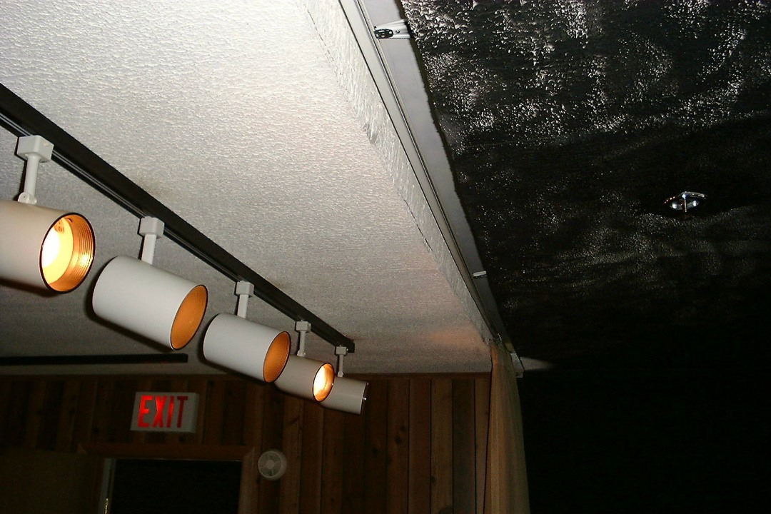
Ten foot track lighting was installed across the front of the room. At each side, shorter (eight foot) track light bars paralleled the side walls. As mentioned, the lights were operated by using R.F. filtered dimmers.
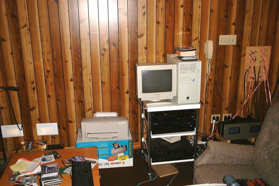
There is one annoying thing in the present set-up. That is the *)@$ noise
coming from the computer's power supply fan! The smaller fans (on the CPU
and at the base of the case) are about 25 Db quieter!

The rear wall is also shown; part of the equipment rack is just visible at the bottom of the picture. The fiber tubes had to be re-plastered in, after fifteen years of use, some small cracks appeared between the vertical plywood covering that masked the drain pipe running down the inside wall of the plant, where it carried the rain water from the roof.
The next shot, may better convey the way the rear wall was arranged. To view a larger and a higher resolution picture, click on the picture itself.
The equipment rack was very heavy. Even though the fixing bolts were retightened
monthly, the right end (as is visible) had a tendency to sink. Retightened
everything required that all the stuff had to be taken off, all the interconnecting
cables disconnected, and everything be moved onto the sound room floor!
needless to say, the monthly retightening became a retightening every three
months - then six months, and finally every two years (or whenever anyone
has twelve hours to spare)!

For a while, we had to check this room every day before we locked-up. On separate three occasions over a period of seven years, an unexpected visitor to the plant was seated in the sound room. However, nobody was informed of his arrival. On the first time that this happened, he arrived just before lunch. I was the last person out of the plant, as I had been working late that day on new tooling design drawings. By chance, I noticed that the fire sprinkler stack alarm was flashing indicating that the pressure was slightly low. (There is a booster pump that we had to use about every three or four months, otherwise I'd get a call at home and I'd have to go to the plant to switch on the booster).
When I was finished, I normally check all the sprinkler heads in the plant just in case there is a drip somewhere. I went onto the sound room and found the sales manager of one of our dealers, sound asleep!
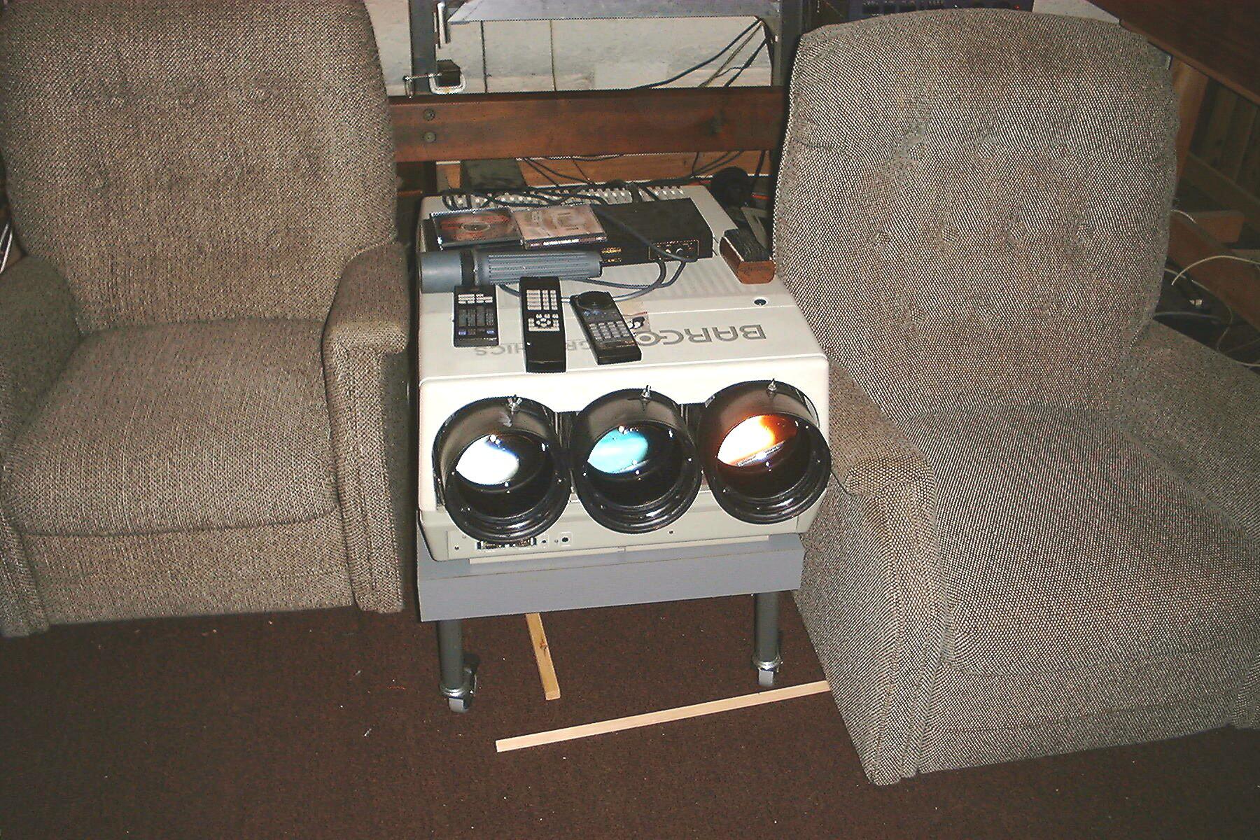
He was a bit startled to be awakened! The reclining chairs are very comfortable, and there is enough ambiance in the room such that, acoustically anyway, it is an ideal place to grab a nap, (we are used to checking ths sound room when we're missing one of the workers!
To continue, he glanced at his watch when he was finally awake (he seemed a bit disoriented - I have always wondered just what he was dreaming about), muttering that he had an appointment with a customer at 11:00 AM, and he was late already. I never found out what happened when he went outside and found that he'd been asleep for about fourteen hours!
Over several years at the same location, we had several requests from aspiring musicians to help them in he production of audition tapes. We had an old stereo Ampex (long since retired) and we'd made some four and ten track studio mixers for people. We had a lot of very-low-noise PC cards that we could use in the construction. We had several different synthesizers as well as an electronic drum set. Primitive to be sure, however as we didn't charge (except for tape), but the price was right! I had done a lot of taping when I lived in the Boston area (including an audition tape for Joan Biez - I have to confess that pert of my motivation was to get back at John Thornton of WTMH who would promise aspiring musicians that he would be 'only too happy to listen - if the tape was of studio quality - meaning that it had to have the proper leaders, solid splices, etcetra). In 1957 that was about $250 of work!
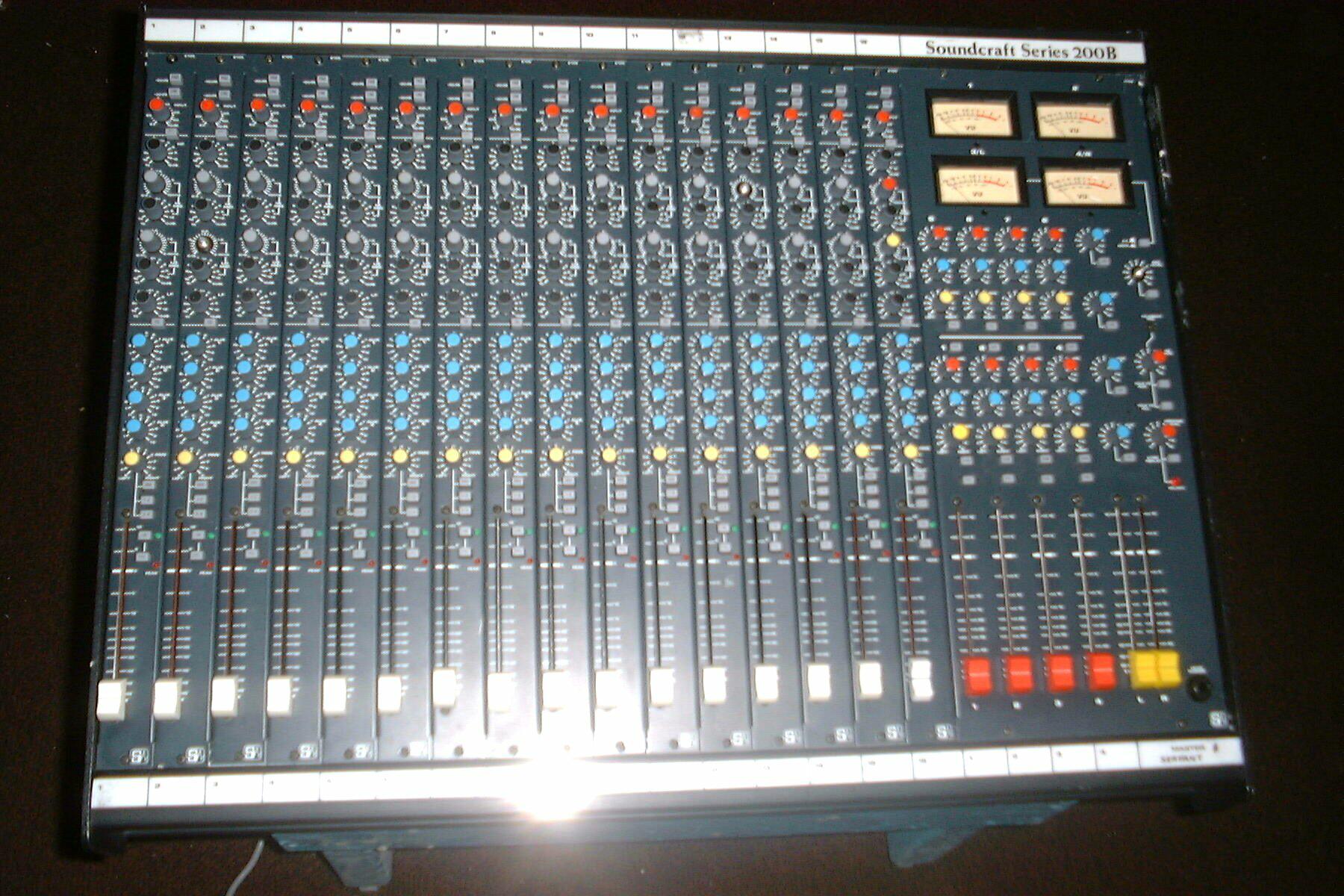
After trying to fit a 24 channel mixer (complete with VU and Peak Metering)
with all the attendant echo, pre-mix, several levels of reverb, etcetra;
we found ourselves spending too much time de-bugging, getting rid of RF
and noise. We didn't have enough room either! We finally settled on an
English AHB 8 channel mixer (as shown). 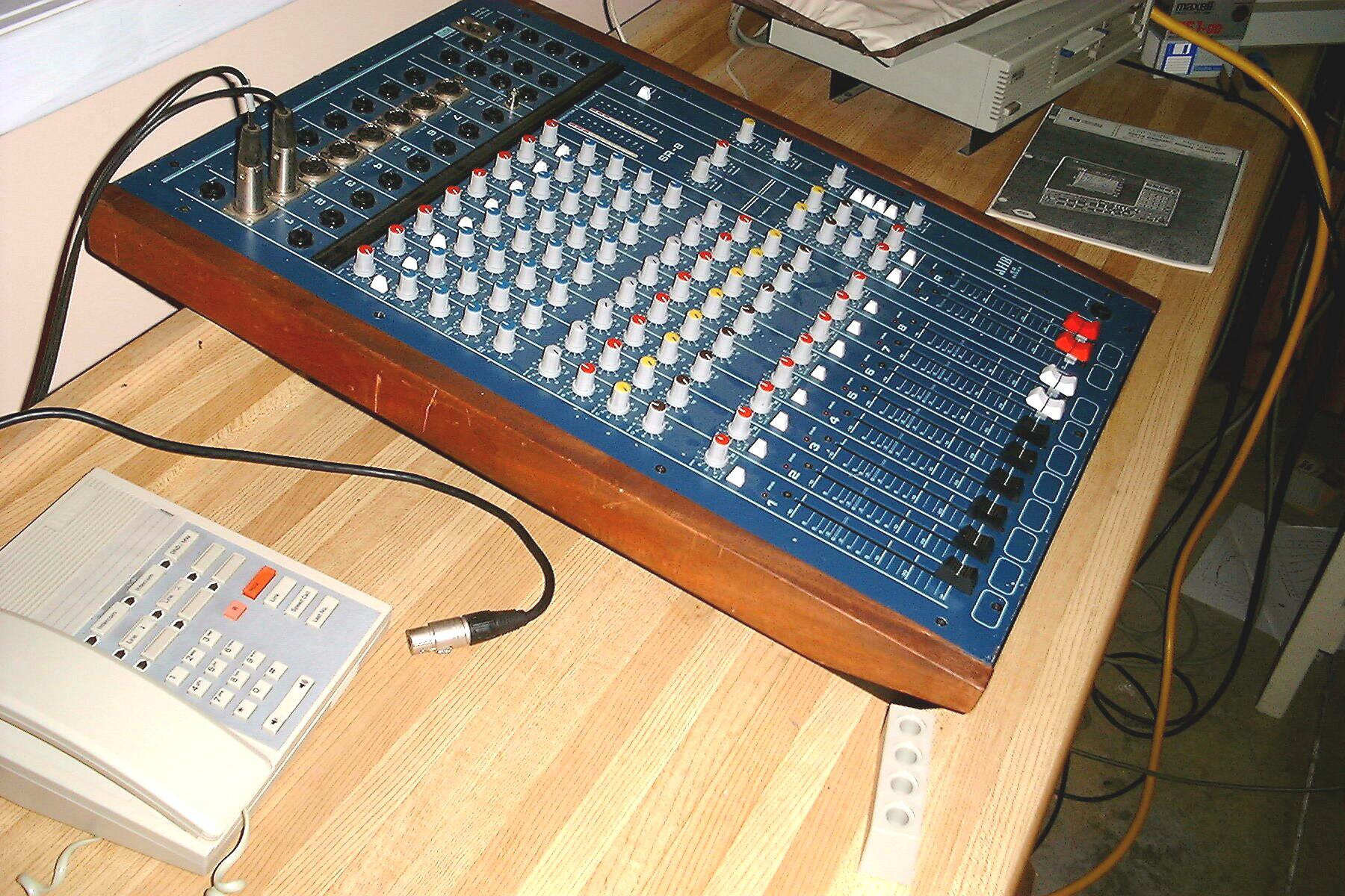 After some judicious tweaking, this provided us with just enough flexibility
for recording on the stereo Stelavox.
After some judicious tweaking, this provided us with just enough flexibility
for recording on the stereo Stelavox.
We installed a double window (having non parallel sheets of safety glass) that was set into separate frames (inside wall and outside wall) with foam strips holding the glass on the inner side. The outer side was pressed against the wooden frame. In order to allow some give to the containing frame, we padded around the safety glass sheets using strips of silicone rubber. The sound isolation through the two safety glass panes was more than we had anticipated!
In order to conduct listening tests, we had to be able to cut off all light
from the control room/lab area, so that it wouldn't been seen in the listening
room! During the constriction phase, we had installed a pair of down lights
on both side-walls. Their lights shone down through louvers in the fixtures.
Every light was controlled by the use of RF-filtered dimmers.

We purchased a Hewlett-Packard Spectrum analyzer together with a Hewlett-Packard 6800 based computer system. This, with the various drives, printers and plotter (s as we were able to procure a used Hewlett-Packard plotter that would handle D sized sheets). All was connected together by the use of IEEE 488 cables. We added Hewlett-Packard function generator to allow us to use impulse testing of all speakers.
As Hewlett-Packard had assured us that they were going to make the system C-Basic compatible, this made the computer all the more compatible as there was going to be a cross compiler available. We spent seven months (usually after seven PM to 3 AM) writing and debugging the software. We developed FFT based software that we could employ foe periodicity analysis. The use of this software cut about ten years of needed R&D programs. We were able to boast that we had already solved problems that other speaker manufacturers didn't realize that they were going to have solve!
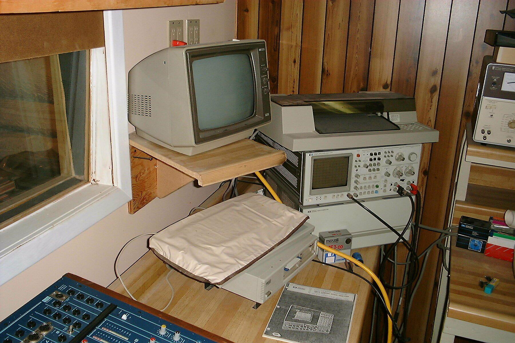
The Hewlett-Packard stuff is visible above, and the window and part of the latest mixer below. We have, over several years of product evolution's, been able to build much of the specialized test equipment and jigs needed not only for R&D, but for production runs. We had to move some of lesser used pieces of test equipment, over to shelves near the lab.
Eventually we bought a British made sixteen-channel mixer that had four outputs and eight auxiliary channels all which had full equalization and panning. This board also allowed us to choose between two or four channel replay, panning on the eight aux channels. It had full talkback and all the bells and whistles generally required for a small studio. This can be used with the eight channel mixer we have been using to provide more flexibility.
Missing tape recorders
We used both a stereo Stelavox and a reconditioned four channel Teac, both with remote control. We added four channels of digital echo as well as a Dolby 5.1 system. We installed the Pro model Acid effects program running on a Pentium !!! 800+ Mhz system. This is in part of the Lab area - its getting too full and we will have to move several storage shelves out of the hallway to create room for all the new stuff! We were so crowded already that we had to install cameras in the sound room to see what was going on inside.
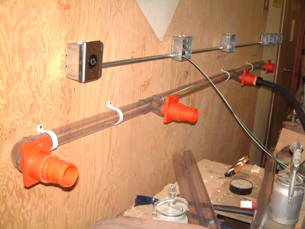
To avoid these, we had to install a 450 galloon double walled isolation
tank (complete with an four foot high sound-proof cover - the end is at
an angle of forty-five degrees and is also sound-proofed). By the
use of phase aligned speakers at ear level (the listener is essentially
supported by blood temperature water in a frame that keeps his head in
the same place during the tests.
Initally, the Isolation
Tank was set-up on the West (front) of our unit. The location was fine
as it gave us easy access to the instrumentation we used. But, the humity
was far too high and even the close proxmity to the test gear didn't make
sound isolation all that easy and all the venting was from the top of the
tank..
We used a pair of HP programmable function generators to drive the two speakers. The system could be programmed to emit the same type of sound from each speaker; however the delay could be randomized. The subject was in the dark and had to try to align a small LED mounted on a frame, by using a soft rubber hand grip underneath the the layer of floating foam, to 'point' at the apparent sound source.
During the initial run, we used every type of sound was used, ranging from single half cosine waves to bursts of ten sine waves. The program tested the frequencies from 100 Hz to 8,000 Hz - all at random if needed. We found that we had to randomize even the subjects' skin sensitivity by using 'pink tactile noise' from air jets in the sides of the tank - much like a Jacuzzi.
The use of tactile noise is also used in treating children's hypersensivity We had a couple of specialists who asked that we allow them to employ our facilities in the treatment. We modified the 'Jacuzzi' jets to allow injection of extra compressed air from an external air compressor. We then modified the 'subject holder' to allow for the aim of water/compressed air jets bypassing the main Jacuzzi jets as necessary.
Several papers were written, however, the peer review thought that the number of tests were so limited, that the preliminary results shouldn't be published. As we were only a third of the way to the completion of our studies on stereo localization, were already behind our schedule.
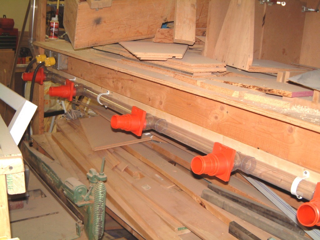
We decided to relocate the Isolation Tank Eastward abutting the Media room.
Although the exhaust wents were still on the top I was able to usea pair
of dryer-venting tubes that ran up throgh the mezzinine floor and used
aluminum tubing to extend them five feet further.

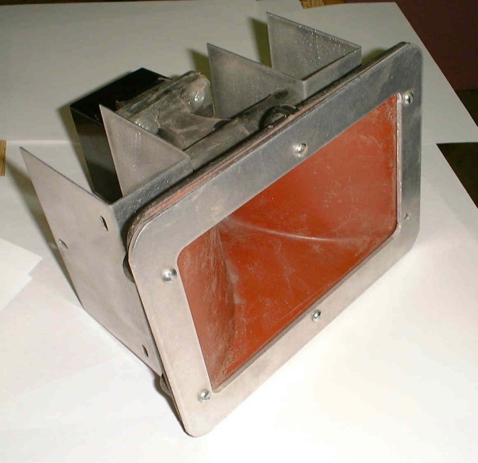
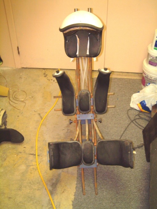 Shot of test subject support fixture.This was supported inside the tank
by a bracket that spanned the horizontal galvaised pipes that ran along
each (interior) side of the tank. This had a dual socked at an angle away
from the tank end. Both water and air were pumped though all the pads that
held the subject suspended in the blood temperature water. The intent
was to create 'pink stimulation' (akin to pink noise). In the darkness
of the tank both the sensation of sound and touch would be randomied
well before any sounds were applied. We selected, at random the number
of cycles (1 to 12), the frequency (30 to 12,000 Hz) and the intervals
(1 to six seconds).
Shot of test subject support fixture.This was supported inside the tank
by a bracket that spanned the horizontal galvaised pipes that ran along
each (interior) side of the tank. This had a dual socked at an angle away
from the tank end. Both water and air were pumped though all the pads that
held the subject suspended in the blood temperature water. The intent
was to create 'pink stimulation' (akin to pink noise). In the darkness
of the tank both the sensation of sound and touch would be randomied
well before any sounds were applied. We selected, at random the number
of cycles (1 to 12), the frequency (30 to 12,000 Hz) and the intervals
(1 to six seconds).
Needles to say, this project could have taken years to complete.
 I realised that I didn't inclide some essentials in the first update, including
the way we were able to insure that the subject was comfortable.
I realised that I didn't inclide some essentials in the first update, including
the way we were able to insure that the subject was comfortable.
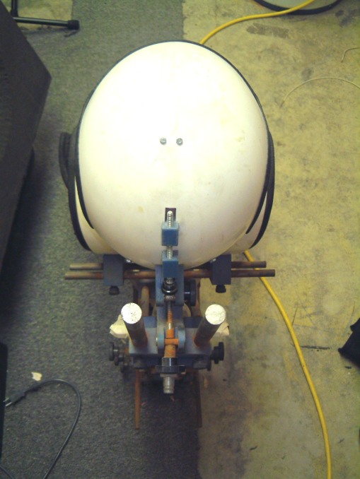
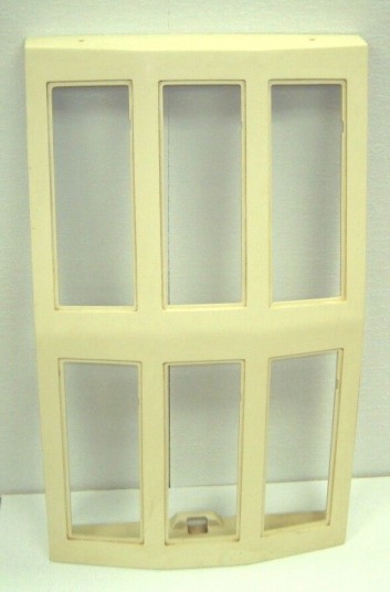
This is the top view of the head fixation helmet. This helmet left the subject's ears free. Floating six inch thick pads were quite effective in subduing reflections from the waters surface, especially after we added more layers of foam, basing it on the further away from the subjects head, the more layers of foam. We let the subject get into the tank and had teathered weights on the ankles so that each weight rested on the tanks bottom. Thus the legs 'floated' free. The multi-layer floating pads thus were in place all of the time from the furthest end to about six feet. The rest were added once the subject was ready. There was an LED target that cound be manipulated by the submerged hands.
The target LED was under the contol of the subject; howener the hands were not directly linked to the LED. The LED was dimmed at first, the subject had tp press a button whenever he believed the sound seemed to come from the LED.and then it was bright.
The response time was meaured as well.
During the proceeding five years, part of which was in the first Isolation Tank location, we had been carrying-on with the project by using volunteers.
This slowed the project too much, but the data we had amassed over the the years, gave us immense insight into the way that the brain processes what it hears - or what it thinks that it hears!
During the initial phase of the research, we had been using paid subjects, However all that change! When even the remote possibility of contracting AIDS from water, this skyrocketed the insurance costs! We had to abandon the major portion of the project and tried to carry on at a crawl!
The tank room didn't affect the clean-room! But we had to get our own heating and air-conditioning contractor to re-install the heating vents.
The final blow came when I was warned by my doctor that I couldn't spend six to eight hours a night conducting tests and operating a loudspeaker manufacturing buisness at the same time.
At the Winter shows, I'd drive down using a heavy rental van. We'd usually clear US customs at The Buffalo Port of Entry, timing it to arrive at 10.30 PM. We'd make prior arrancements to use C.J.Towers for brokerage faxing them in advance with our Custom Form paperwork. We would always have extra paperwork as there always seemed to be three to five needed cartons to put on the Exhibit. However clearance never seemed to be a problem. We'd have arranged in advance to pick up one or two university sudents (who we paid + room/board + a spending allowance. We usually had made an arrangement to bring two of the Canadian DW dealers as well. They had the same 'benifits' as our people. On the way back we'd stop over in Phoenix for a week to ten days. I had arranged to purchase an essential metal tool such as a milling machine, a lathe or the type of rubber mill used in R&D.( We had a rubber press already).
When we took over from Leigh operatng the Speaker manufacturing buisnessat our plant was at times harrowing, when I was involved in getting the full scale manufacturing of Stabilant from an office just north of highway 7, and monitoring the loudspeaker production at the same time was hell on wheels. I began to get concerned as until 1986, some of the workers at The Dayton Wright Group Ltd., were used to going to the CES show in January each year where it was held in Las Vegas. In the summer, it was held in Chicago where I could fly down to Meggs Field to land.
Now I had to split my time between two business. The full time Stabilant started in 1996. Within three months our new CEO had overspent the allocated budget by $55,000! We were heading for disaster. The new CEO had screwed-up our US market.
By Christmas time the Sales of Stabilant had dropped by 45%. Then we got stuck with buying back an insured shipment that was lost for 14 months. If we hadn't got it back, it wiuld have been 'dumped' on the US market at a 60% to 75% discount. We didn't even know it it had been tampered with. I had to 'bite-the-bullet', get it back, then destroy it! We had a hell of a time for more than a year. We had to settle a claim by our former CEO that depleated the budget by $11,000. Then we found that we had to return $10,000 to a shareholder that was listed in error as having $20,000 of shares.
Then we were kicked out of the Downtown Head Office for the error.
We had to move to The (Italian) Bank of Livorno. There we were forced to
pay 6% above prime, and didn't know if our checks would be honored as the
bank took out it's interest first!
We eventually moved up to the Bank of Nova Scotia in Richmond Hill where I arranged for a line of credit for $60,000, with me as the sole signing officer. The ESL and Cone type speaker business was doing very well and we could project a profit of $124,000 for the fiscal year.
But somebody had been shipping over 75% of the production out the back door!

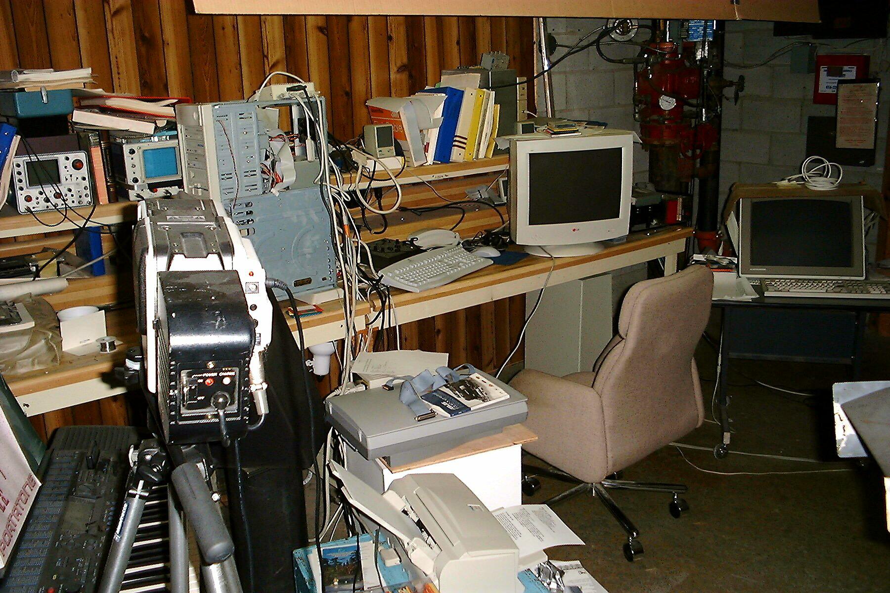
This set of shots, were taken this spring (2000) and you can see how we've had to cram in several more computers into the R&D section of our plant.
In 1996, we purchased a BARCO Graphics 400 projector to be used in our sound room. We hooked it up to one of our lab computers (a 333 Mhz Pentium II with a ATI All-in-wonder pro AGP video card, a Soundblaster 32, with an Encore DVD player. We used a wide bandwidth unity gain buffer/isolation 'amplifier' to drive both the 19 inch monitor in the lab and the BARCO projector in the sound room. As the BARCO was able to handle a resolution of 800 x 1024, this lash-up worked very well. As the ATI card would handle interpolation very well, it provided us with almost the equivalent of a $14,000 Farodja line doubler. We used it, occasionally, for the production of custom DVD's with the Yamaha SCUZZI CD burner.
We used the several power amplifiers we had acquired, but we found that Dick Brown's bridged stereo amplifier gave us the most glare free sound on the Dayton Wright XG10 Mark III's. We were using other speakers as well, from the Japanese model of the Watson 10 A's (which was the only pair we were able to recover from a San Francisco dealer when the whole Japan bound shipment was stolen from our plant in 1978). These Watson speakers began to appear in the 'Bay' area about eight months after we had to close-down Watson Labs!
Remember, we bought Dayton Wright from Leigh in 1980/81.
Dayton Wright Group Ltd., not only produced ESL's but cone speakers. Therefore we set-up a quality assurance system for both the ESL's and the cone speakers. By 1982, every speaker we produced, had to be tested for phase, frequency response, distortion (both harmonic and TIM) as well, after 1985, we tested to destruction, one speaker out of twenty-five! This was needed as we found that AUDAX in France, was mixing their stock of high-temperature-fusing voice coil wire, with the low-tempeture-fusing magnet wire that they may have been using for cheap crossover inductors!
Several times, we had to suspend production of some of our cone speakers when we acceptrnce-tested The speakers an found a very high failure rate. When we stripped down several speakers in the sane batch, we found that some of them were the speakers with the low-tempeture-fusing magnet wire.
We worked with another manufacturer, in Poland, to obtain the same Bexidrene cone with a butyl surround similar to what Audax was supposed to be shipping. But that is another matter!
We had developed several sub-woofers. This started in 1969, when we were trying to produce a small woofer system by using the ideal gas characteristics of SF6 (Sulfur Hexafluoride) which, as it has a speed-of-sound about one third that of air) enables a designer to almost cram a twenty-seven cubic foot box into one cubic foot! We built a dual ten inch speakers into a SF6 filled corner enclosure and named it "The earthquake Pill"! We built some forty speakers between 1969 and 1973, sealing the speakers so that they could not be opened without tearing the "empty" gas bag!
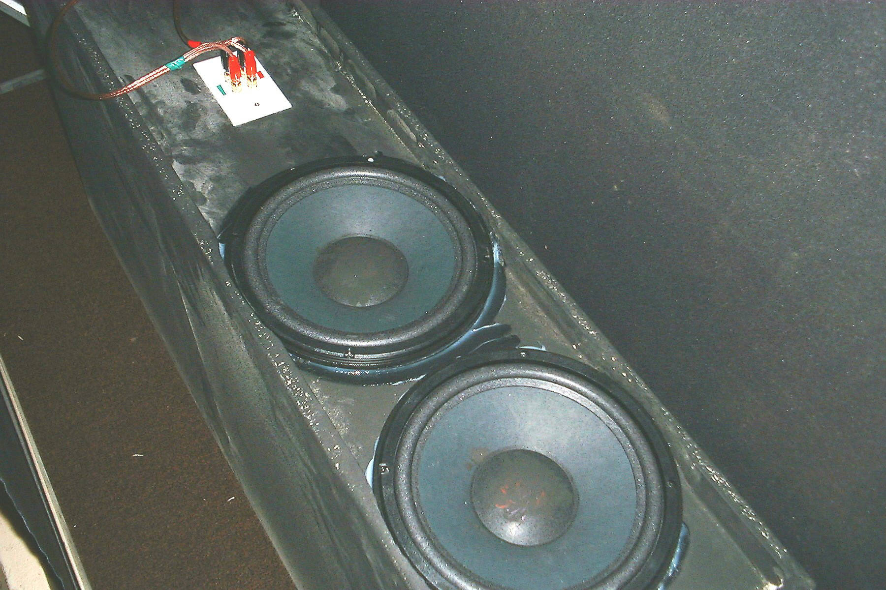
There are two sub woofers at the front of the room. Two old stereo power amplifiers drive them. The subwoofers are the same as we used in our ICBM-1's. As they are flat to 15 Hz and are not easily overloaded, they are very effective on organ music, of for that matter, the sound of the dinosaurs in Jurassic Park!
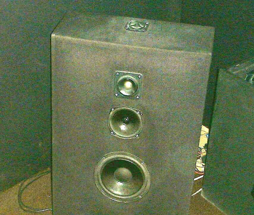
We normally use a pair of XG-11's with a center mounted horn. These speakers are canted back by our use of a pair of ball castored stands (about fourteen by two inches in cross section and nine inches high (plus the height of the castor). As shown in the picture. the front speakers are four way time aligned phase-coherent, using Tonsil nine inch long throw woofers, Focal stacked magnet five inch mid-range units, a one and a quarter Tonsil soft dome tweeter and a three quarter inch upward firing super tweeter. The crossover is a modified Gaussian design with the super tweeters on a delay line to align then in phase at ear level.
The center speaker was built in a JBL box with a wide-range Focal unit
on each side of the tweeter. The tweeter is mounted with a layer of 'carved
felt' modifying the dispersion at the front.
However, to return to 1996, setting-up the (analogue) BARCO was a real pain, as we had to re-converge it every time we had to move the screen. In addition, that model BARCO was not very bright.
We decided that the leads from the computer lab into the sound room were too long. Because of RF interference in the location of the plant, we were having problems with some of our computers. We were operating them o UPS's and surge protectors, and the telephone lines had been checked as well. Still, we decided to add two more computers; one could br running Linux Ver. 6, and the other one would be installed in the sound room. It would be a 600 Mhz Pentium III with an ATI 128 card that would also handle DVD's. We would be able to compare it to the latest Encore DVD card. We would use a Sound Blaster Live (X-Gamer) card which would support all the DVD modes as well as rear (sorround-sound) speakers (using LCM-1A's on the rear wall. By the use of special switching we would ce able to compare the best analogue sound with digital sound!
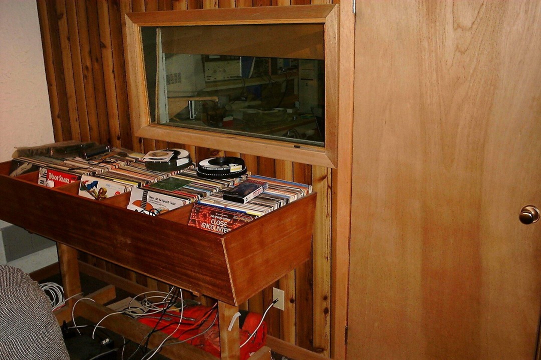
A rack was set up on the side wall. The down lights are visible here to the left of the printer.
The control-room/computer room is outside this side wall. Both the window and door are on this wall. Part of the collection of record albums are visible!
This slight amount of
reorganization made it a bit easier to use the sound room. In the all the
years in the plant, we still hadn't been able to find the time to snake
a set of microphone cables though the back wall of the sound room.
We had to use the spare port for the Sony camera cable. It has a separate
camera control box with a talk back to the cameraman. Eventually, when
we have the time, we plan to build a separate video room and move all the
cameras in there (real soon now as they say)!
When we found that a digitally based BARCO Graphics 800s was available,
we bought it!
In the fall of 2001, we were able to purchase a Barco Graphics 808s with an Iris3. We have decided that as the older 800s was supported by a caster mounted floor stand, it as too low to align with the screen. No matter how we set it up, the screen was too high; we cut off about 5% of the picture at the bottom. In a rash moment, I bought a mounting that would allow me to suspend the Barco from the ceiling. We were able to reinforce the mezzanine floor (It is used for storage anyway) so that it would be able to withstand the 140 lb weight of the unit plus its hanger.
Now, we will be able to reach the computer stand, without tripping over cables lying on the floor! Well, we hope! I hate to say it, but Max's creation will have to be moved out of the sound room. However, for now at least, we cannot get at it to move it - there are far too many wires and cables intertwined with it. I have to borrow one of Jerry Pournelles' phrases to explain the delay. The required move will take place "real soon now"!
By this time, as you can see, the lab was almost unusable for lack of space. Besides what can be seen here, we have a '486 DX 2 computer running on DOS 5 and Windows 3.1 We haven't ever had any problems with it since we built it in 1993. We are running Visual basic 3 on this computer as well as the DOS version of FoxPro! It uses a Electrohome 19" monitor. It was built to run an ATC (Air Traffic Control) program using a null modem link to Flight Simulator Ver 4 running on another computer. At trade shows, we were running a computer housed in a plexiglass case filled with Stabilant 22.
We had several 800 line resolution TV cameras. We were trying to accommodate the Stelavox stereo tape recorder with its ten and a half inch reel adapters, several preamplifiers including several ultra low noise DW prepreamplifiers, a SOTA Sapphire vacuum turntable mounted on one of Max Gottchalk's equipment racks.
Throughout this period, we had to move D. W. Electrochemicals Ltd., from its office on Leslie Street, up to the space we had on Newkirk Road! We essentially rebuilt the offices, carpeted the floors, and painted the walls. We had to build a packaging/bottling room (with filtered, laminar flow air) in the plant. During all of this, we were writing an ISO 9001 manual! (We passed the review with a score of 73 % - the first time!)
Of course, we had to cope with unanticipated problems. That comes with the business. We found that by careful planning, combined with the extensive use of 'dedicated' computers (we had five simpler computers instead of two networked computers), we were never bothered by crashes. As backup, we would have the same software available on the backup machine - on a different drive partition as well!
One of the results was that we didn't ever have a YK2 problem. When we wrote the software, we never fell into the trap of two digit years. As we set our own field length, it was easy for use to use a four digit year!
Things to come, with some uncompleted speaker designs:
Project x-tube - weird name, but it seemed to fit:
This one seemed (at the time) very promising. It was based on a cabinet design that used 5/16 inch thick 4 1/2 inch diameter fiber tubes, sawn into quarters, as the vertical edges on the front corners for the speaker cabinet. It would employ stacked leaf tweeters (at a slight angle) with a stacked horn for loading. We had a shorter horn (another distributed cut-off design) similar to one we had used on the electrostatic tweeter, below.
Obviously, this is too large to stack but by shortening the horn (40 %) we were able to stack the two. We used a pair of Focal five inch speakers to cover the mid-range from 6 Kz, down to ~ 120 Hz .But, first, more about the cabinet itself. It was made of medium density fibreboard, 5/8" thick. As we had to allow for a 5 1/8" mounting flange on the Focal drivers, and another 4 1/2 inches(total) for the quarter round fibre tubing, this made the speaker cabinet (if it was a paralpiped rectilinear, which it was not), that meant that the cabinet would be about 8 inches wide + the allowence for the 5/8 inch of felt or about eight and a half inches in width. That would not privide enugh room for the deeper-than-normal woofer. However, by making the cabinet five inches wider in the rear, we could shoehorn the woofer into the enclosure. But, we had to play a "trick". We cut an opening for the magnet on the other side. Since the woofer was inserted from outside the enclosure, this allowed it to fit. We used a semi-squared-oval flange on the woofer. This allowed us to use outside threaded cast-inserts to secure the woofer ( we used the same inserts on the bottom of the cabinet). we sealed the magnet to the cabnet with silicone. This resulted in a strong enclosure!
With the angled sides, we were able to allow enough allowance for the quarter-round edges so that they didn't have to be sawn square! We rabbited the outside edge of the front and sides of the enclosure and were able to use a jig to align the top, and sides in place. We cut the jig so that it would pre-load the quarer-round edges and used four loop of rubber tire tubing as clamps. When the glue had set, we extracted the jig from the rear, and inserted the back panel. Remember that the cover for the speaker enclosure had to "snap" into place. We were able to locate four retainers on the enclosure and the grill cover, under the cloth, so that the felt was pressed firmly against the enclosure. This design was easy to veneer as the groove for the open (stiff) plastic sub grill was in a logical place. We even were able to locate a wood similar to rosewood that we had cut into quarter-rounds for the top edges of the enclosure. We used a seven inch Focal driver for the upward and rear-slanting ambience speaker. There was a similar cover for that driver. The grill fit into a groove on the top and the cobering grill cloth was pre-stretched and fused over the cover. This was the first design where we used a hot-melt adhesive for a grill.
To return to the woofers, they crossed over to a 10 inch long throw (using a three inch diameter voice coil on a Kapton former. The suspension was "different" in that we had to employ two rear suspensions, the outer one was a Kapton spring in eight 1" sectors (with a crossed spring design) with openings between the eight sectors. The inner one was a near normal corrugated suspension. We had a large ferrite magnet (more than twice the usual weight) as we had to allow for more gyration on the cone assembly. The woofer (had 9 SF6 filled bags) in its enclosure. The LF resonance was about 18 Hz. Even with a bag over the woofer, its HF response matched the mid-range. We used a modified Bessel function crossover between the woofer and mid range. We placed the tweeters at the center of the cabinet with the mid-range speakers above and below the stacked tweeters. We found that the sweet spot with the speakers needed a seven degree tilt-back and the cabinets had to be raised eight inches from the floor. We used a set-back of four inches that seemed appropriate for design. Now, I must add to the design; we covered the cabinet with 5/8 inch of felt, leaving the mid range and tweeters uncovered. We found a perforated plastic with wide openings to support the grill cloth.
As I noted, we decided to add some wood to the design. The set-back and the rear four inches were finished in Rosewood veneer. The grill was snapped onto the cabinet with the felt as part of the grill assembly. We employed (on a 15 degree tilt-back), as I said, another Focal driver for ambiance - running these two speakers in series across the "hot" output terminals of the power amplifier. We used foam disks for an inch around these drivers and pressed the cover assembly into a groove on the slanted rear of the speakers. The Rosewood veneer was also used,; it tied in the wood with the cabinet. We had to make a modification as the obtainable veneer was about 3/4 of an inch short; so we added a half inch set-back to a dull black finish medium density wood fiber to act as a base. We used 1/4 - 20 threaded inserts on the bottom, so that we could use either glides or points (that could penetrate the carpet).
We sent two pair of these speakers out for audition. In both cases the audiophiles wanted to buy them. We left them for a month before we needed their return to compare with a farmed-out set of prototype cabinets.
We were delayed by the loss of twelve 5 inch Focal drivers that vanished from Canadian Customs bonded warehouse after clearance. We had enough for a single speaker (remember we needed three Focal units for each speaker system.
Another disaster, our supplier of leaf tweeters had a shipment delayed - he claimed that the container had water damage and he said that the replacement "might be" another month - or two, before it was at his warehouse.
As that meant that we would miss the Las Vegas show we had one pair crated and shipped to us at a hotel in Phoenix where we could stop on the way down. As the rented station wagon was tight in space. (The reason for not shipping exhibits to Las Vegas shows is that the warehousemen are notorious for smashing exhibits.)
As we could cram another body into the station wagon for a three hundered mile trip, from this seemed logical. We made arrangements to stay at hotel close to Phoenix on the way down, and to stop for a week on our return. Alas, although we called several times. we had no luck .We had insured the speaker system anyway.
Then we attenpted to expidite the shipment of leaf tweeters. We must have driven the dispatcer nuts with all the calls. The shipment of speakers was traced as far as Omaha, but it went missing after that! We called all the connecting transport companies. No luck. We had to cancel the booking to the Las Vegas show This cost me several thousand dollars even though another exhibitor took over the booking.
The leaf tweeters never arrived and the "replacements" had a different mounting arrangement so that we would have to re-tool to match the new design.
However, there are some people that you connot please. A certain dealer in Phoenix started to libel me , accusing me of being too "chicken" to show up for the show. Now, the libel laws in Arizona are very strict. My lawer (in Phoenix) wanted to take Mr. H., to court. But he was being sued by the customer that had bought the SPA preamp that had been blown by a lightning strike near his home. I was subjected to several months of harassment when we wouldn't replace his SPA for free. We pointed out that, under our warranty, we are not liable for eqiuipment damaged by lightning. Normal home owners generally take out insurance that wil cover them (sometimes) against lightning strikes. As we cannot control the insurance policies of our customers, we, as do most manufacturers, deliberatley place exclusions in their warranties.
Mr. H. was sued by his customer. He won on the basis of our warranty But, that didn't reverse the effects of his llable! Small ethical manufacturers are especially vulnerable to such forms of harassment. I know of seven small forms that had to close up as they didn't have the capital to pay the legal costs involved. In the US, esprcially, many lawers will accept dubious cases based on contigent fees. Unless, you can afford to lay out ten to fifteen thousand, US to retain a laywer, you cannot survive. Nuff said.
About the same time, we had embarked on another ESL project. I had designed a different ESL. Well, to clarify this I wished to Pussycat proof our ESL's by increasing the space between the front Mylar diaphragm abd the grill cloth. If I could reduce the spacing stretching the outer Mylar over an inner self-skinning structural foam cabinet I cound move the Mylar almost three inches further away. I also wished to manufacture a double inner cabinet with a single row of five or six leaf tweeters mounted in a vertical line between two 6 cell arrays (three cells horizontally by two cells verticaly) (or a doubled 3 x2 array with a vertical row of leaf tweeters between).
This had another advantage; shipping. The XG10's were difficult to ship as although we shipped a stereo pair on one pallette, some trucking companies would unband them to reduce the weight to half; this meant that a single person could handle a single box at a time rather than using a fork lift truck to load a pre-banded pair.
This would make it easier as the cartons containing the pre-packaged self-skinning structural foam modules weighed 28% of a single XG-10. OK. There are ten cells in a XG10 rather than the six cells in the new design. However the weight of the steel cabinet is more than you'd expect.
I have taken some photos of the pattern but I don't have the four ESL arrays and the stacked leaf tweeters we used. I had to assemble then in another location and, during the five-month we were making arrangements with the bank, someone smashed the lock on the storage unit and stole the new ESL's.
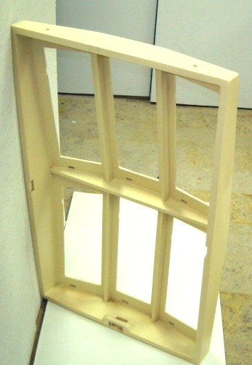

The recess for the cross-brace can be seen half way up the side of the pattern. Also, note that the mounting for the electrode and bias connections are shown at the bottom center of the pattern. The recesses needed to clear the front electrode are also visible. This pattern was machined in medium density board and the appropriate urethane-modified epoxy glue was used. The pattern is finished with another epoxy and should withstand extensive use tin the production of self-skinning structural foam.
The outer cabinet could be shipped as a kit complete with the grill cloth. We could use self-skinning structural foam to mold the six pieces needed to assemble the mid-frame as we called it. There were four pieces of veneered self-skinning structural foam that comprised the visible trim.
We found that with more of the SF6 gas at the rear of the cells there was a larger phase shift; more like the old wooden cabinet XG-8's. We were astounded at the increase in low-frequency response until we thought it through. The time delay in the one-and-one-quarter inch of SF6 at the front was much less than the time delay in the (average) of four-and-a- half-inch of SF6 at the rear. The 'Q' at the front was very low while the 'Q' of the broad-banded resonance at the rear was wide.
We designed the inner cabinets to be cushioned on a one-quarter inch of sound absorbing felt. Each 2 x 3 inner cabinet was packaged with a 2" spacing, front and back, in a double corrugated carton.
We incorporated the two 10 inch sub-woofers into the step-up transformer and high voltage supply (using a high-frequency voltage quadrupler power supply - similar to those empoyed in computers). The combination of sub-woofer, step-up transformer, crossover network and high voltage bias supply fit inside a 12" x 36" x 16" cabinet that was (optionally) located at the rear of the ELS's although it be under the ESL's.
I started to use RTV silicone moulds back in 1958 and actually taught the tecnique to engineers seeking quicker ways to produce epoxy (and other castable resin) prototypes. You see, fast prototype production is part of the essence of R&D. When a part is made, all sorts of unexpected factors become obvious. This in no way detracts from the use of Cad/Cam in design; both have their place.
This is why, when I started to produce, even such tings as butyl rubber
loudspeaker sorrounds I bought a small rubber press, and used the lathe
and milling machine to make small corrections in the thickness of parts
of the sorround. This allowed us to mininise reflections in the outer sorround,
and when I produced custom tooling for the inner sorround, I was able to
pick a type of material that combined the requisite stiffness, duribility,
environemental stability and damping that was needed.
With all the losses, we had to shelve the projects. It happens!
Room_Construction_.html
We
will, as time permits, include some suggestions for planning a room to
be used for listening - video. The suggestions will be based on thirty
+ years experiences in the design and construction of such facilities.
![]()
Machine Shop:
One of the most important factors to be a success in R&D, is the ability to construct a workable prototype quickly! Some things are so obvious in a prototype, that days, if not, weeks of CAD CAM work can be saved. In some leading engineering universities, shop work was a prerequisite. It sorted out the achievable from the idealistic perfectionist! By doing this it liberated engineers from wasting time on flawed designs; they could spend more time on creativity!
We have a lathe; including collets, 3 jaw scroll chuck, 4 jaw chuck and faceplates. We have steady rests, grinders (internal and external) boring bars, several different typed of tool holders; in short. everything that is needed in a shop We started by producing molds for the production of butyl loudspeaker surrounds. Within a year, we started to produce spiders as well. This allowed us to produce special double suspensions for extremely long excursion sub-woofer systems.
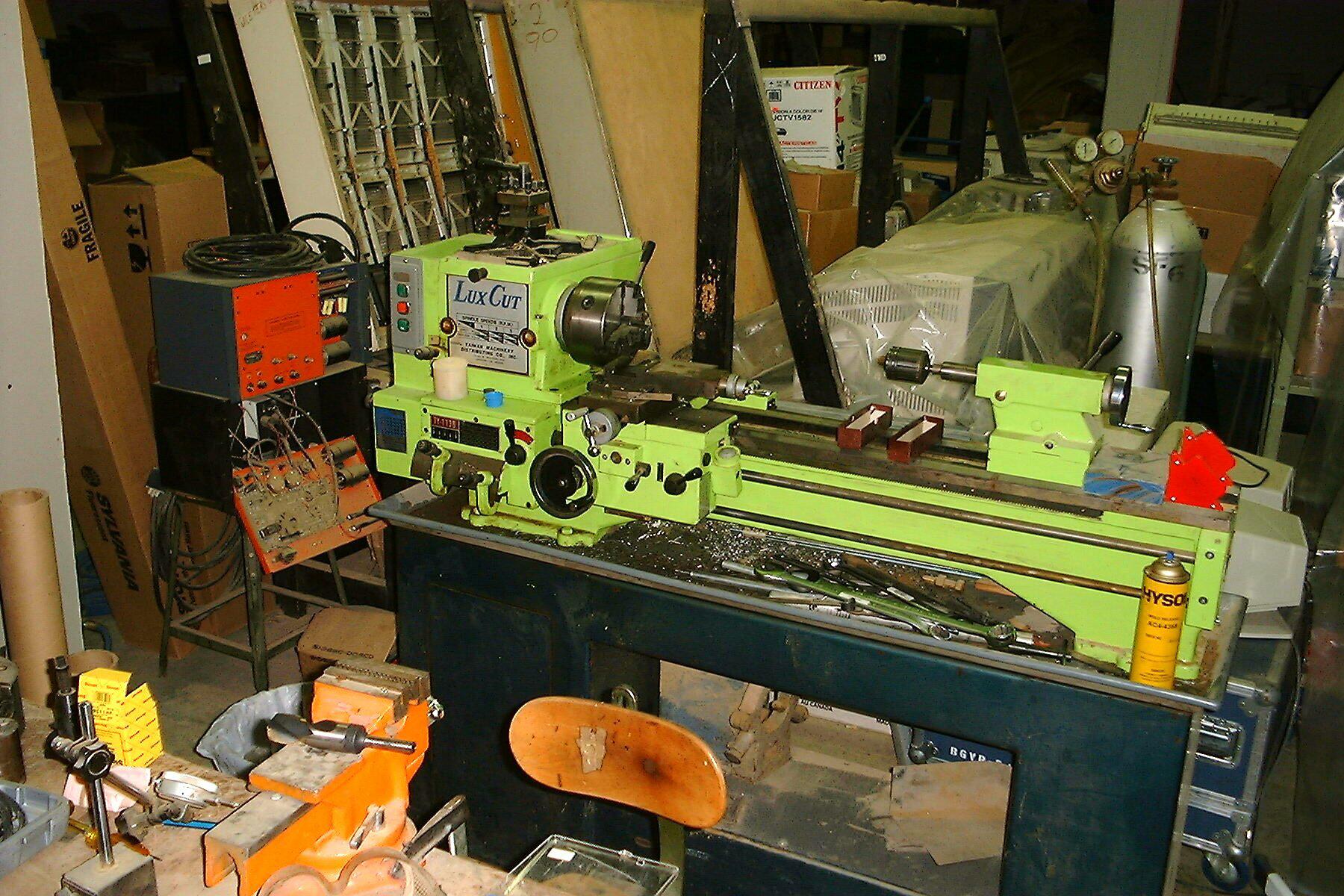
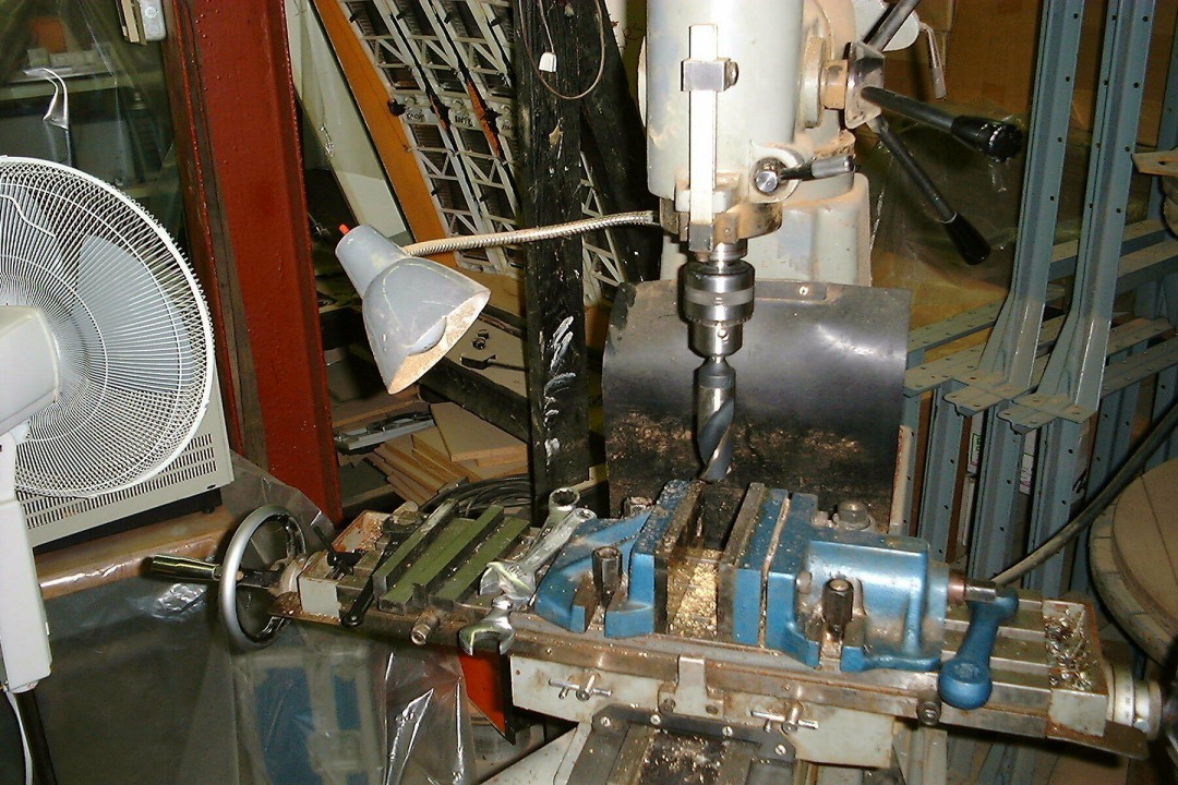
Beside the lathe, we have a small milling machine (complete with hobbing attachment), an assortment of vices, indexing plates (both vertical and horizontal), two sets of collets, over sixty milling cutters two dozen facing tools plus all the angle plates, Jo blocks, deeming and high speed drills, reamers etcetra; that might be needed even for the production of rubber or plastic molds. In 1964, we started to use RTV silicone rubber to cast plastic (epoxy) parts. We found that we could even make silicone molds from stereo recordings. By the use of the proper vinyl plasisol we could produce accurate duplicates (one sided of course). We had to set aside a separate area to work on silicone materials due to their effect on electronic connectors.
We maintain a set of micrometers, venires, set-up tools including a surface plate, set-up buttons; for both metric and imperial standards. All gauges are re-calibrated on a schedule.
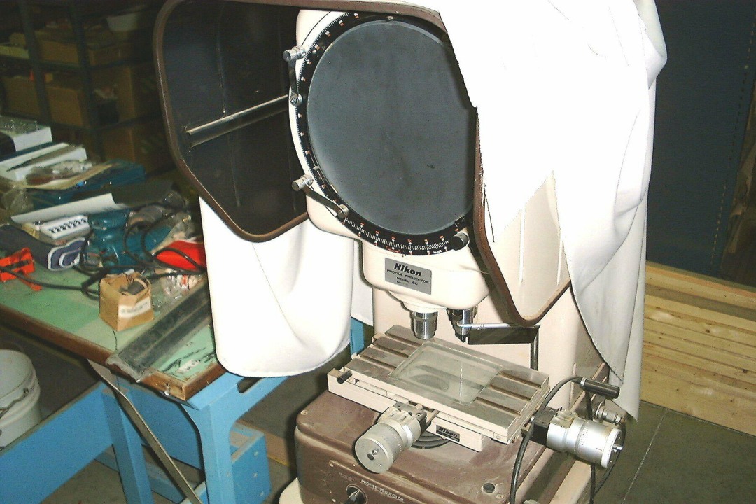
In 1990, we purchased a Nikon optical system for use in profile milling and grinding. We even have used them to produce tooling for short run small aluminum extrusions. Because of the arrangement of lenses and heads, we are able to use optical gauging in many ways we hadn't thought about. As the optical micrometers are large barrel units with coupled digital readouts, they are easy to use!
Every so often, we get a request from a manufacturer in the area, who doesn't have a maintenance shop, to repair something that is needed to resume his production. Then we start to appreciate our facilities!
As we have to re-calibrate and/or test all gauges to be sure they are in compliance with accepted standards, we keep some things separate so that they can be used; if we suspect that a gauge is wrong, as a 'quick' standard. Only when we have to be absolutely sure that a tool has to 'fit' another system, do we have a set of (for example) a set of 'Jo blocks' tested to a Canadian Secondary Standard. Such occasions only happen every two or three years. However, we keep a full set of records anyway!
It, I think, is needed, so that it keeps us on-our-toes! It also helps
us to guard against complacency.
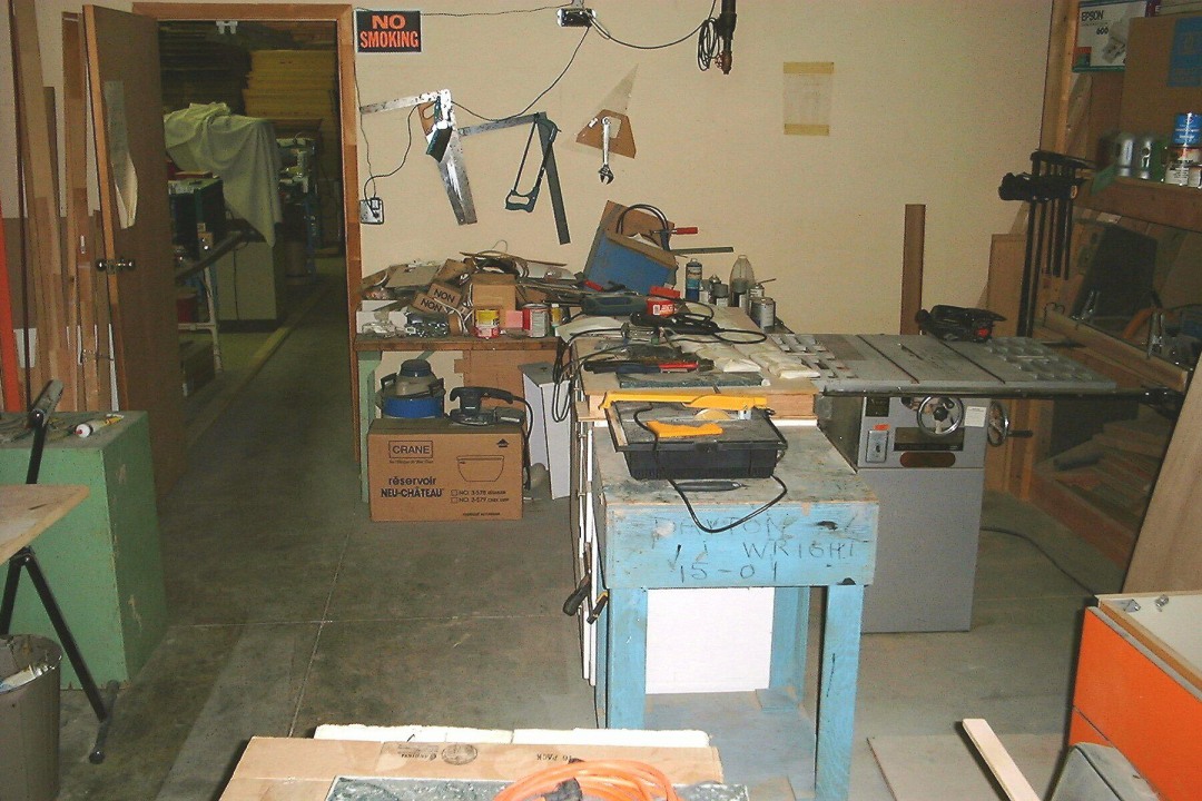
Carpentry Shop:
As part of our facilities, we built a well equipped carpentry shop. We
were thus able to construct prototypes, on site. We were even able to mold
butyl speaker surrounds. The shop was equipped with a ten inch 2 1/2 HP
saw, a radial arm saw, a miter saw, a diamond saw for ferrite magnets,
a floor mounted router, a planer and a thickness planer. In addition, we
had several belt sanders, a floor mounted belt sander a drum sander, two
band saws and a drill press! Every so often we have to round-up all the
various clamps. We have both spray painting (for lacquers and enamels).

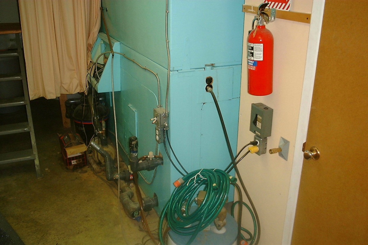
In another area, we have silk-screening facilities. Adjacent to the machine and carpentry shops, we sandblasting and both arc welding as well as oxyacetylene brazing. Everything comes under the scrutiny of security cameras. If anyone is injured they can summon help by pressing an alarm button. All areas of the plant are sprinklered; and there is a fire extinguisher within fifty feet! As we have a lot of electronics in the plant, all the extinguishers are large CO2 units. The rationale is that the speed of response is paramount; staff should not have to take the time to choose what type of fire extinguisher has to be selected! As there are so many available, there is always another one nearby!
In thirty years in the various plants we have been in, we have never had
a serious injury. The commonest injury is a minor cut or abrasion. Even
so, we can go for years without injures. We have an eye wash fountain as
well as a flood shower. All solvents (even spray cans) are kept in UL approved
steel fire cabinets. We use special fusible link type containers for rag
storage and disposal. All compressed gas cylinders are carried on appropriate
carts and all cylinders are chained in place. Even the storage cylinders
are chained in place by an exit!
We have found that, in the almost twenty years since we moved to this plant, our ability to fix things on site has been an immense help. It allows us to modify fixtures to make them more efficient or easier to use. Although we purchase the raw materials and pre-cut parts, to well defined specification; as is the case with many smaller manufacturers, we find that some suppliers cannot always meet the specs.
During the last thirty five plus years, (starting with Hydrospace Developments Ltd.), we accumulated a lot of plant, including a rubber press (and even a rubber mill), however, as we were able to obtain custom stock to our specs, we sold the mill. However, we made our own butyl speaker surrounds and manufactured elastomer speaker horns. We were able to make curved entry and exit bass-reflex ports for several years and supplied other manufacturers with short runs.
When I was operating Hydrospace Developments Ltd., I used my knowledge of making castable plastic parts quickly to assist other manufacturers to make prototype parts in their R&D operations.
![]()
These shots show the revamped carpentry shop area. The upper left photo shows the temporary support for the new wall cabinets. We replaced a sturdy (and too heavy, cast iron frame table we got from Leigh (as part of their junk), with a 11 foot long kitchen type counter top. We reinforced it as needed. Above it, we found two Ikea cabinets, each about 44 inches long. We had to install both of them well before the 'Leigh' table was removed. Therefore, we had to build a temporary supporting frame first. With this screwed to a 8 ft long piece of 1" x 3" (in turn, screwed to the wall studs), getting both cabinets in place, was possible. We had to avoid some sprinkler pipes.
The upper right shot shows the upper shelf with the 2" x 8" vertical posts still in place. You can see that we haven't cut them off. The lower left picture demonstrates the over-crowded area where we were working. The lower right shot shows that we have finally been able to get the new counter in place (with the drill press).
Lighting was always a problem; so we installed a pair of fluorescent lights under each cabinet. In the process, I decided to tear down an eight foot long section of the sixteen foot long speaker storage rack. When it was first built in 1981, it wAS OK, but by 1999, it occupied too much space! However we still needed the sixteen foot + top shelf. There was only one thing to do. I had to run a 2" x 6" extent ion through the wall, and attach it to the steel storage rack units at the far sides. There, we have well over thirty-six feet (by twelve foot) of storage; strong enough to support the cantilevered unit. Remember that the rear supports are still there. With lots of lag screws, I was able find enough overlap so that the now 4" x 6" unit is very strong. This allowed me to 'create' enough floor area so that I don't have any problem ripping a eight foot long piece of 5/8" medium density fiber board all the way!
I was now able to install a eight foot long fluorescent fixture under the upper shelf! So, bit by bit, we are 'migrating' pieces of stuff to where we need them! Doing all this, while we have to operate another business, is frustrating, to say the least. But, to paraphrase the anally retentive, "This too will pass!"
The revised layout too longer than expected as I found much that had to be rearranged. I decided that having BARE concrete block wall seemed an invitation to use it for shelves. As the photo shows, I was able to erect three shelves. To prevent heavy electrical (and pneumatic) tools from being pulled off, I added a raised lip at the front.
Well, sooner or later, some things cannot be put off for long. So it was in our carpentry shop. We've been enduring dragging sixteen foot long 10/3 cab-tyre "extention cords" with their Hubble Twist-Lok connections, over to saws or sanders ao that they'd work. I realized that it might be easier if I installed enough outlets so that every "heavy" power tool had its own outlet. It then dawned on me that I should install a dust collection system; for the same reason that I'd used for electrical outlets.

Well, the reorganization began, well enough, at the beginning. But, before very long, I found out some things that, accoding to my standards (always exceed the applicable code). For one thing, my ten-inch table saw used to have difficulty in sawing seasoned oak four by fours (inches, not meters). I knew that this grade of oak can have ingrained wracking (both sides of a center-ripped plank can twist in different torsions - one side twists clockwise and the other side twists counter-clockwise). As I didn't have room to install a planer or a jointer, (yet), I would have to insure that the existing table saw and table router had adequate power. I traced the supply back to the circuit breaker box, and discovered that both of them had been on a single fifteen amp breaker. When I had an electrian install the wiring (it had been inspected and passed) there were three free fifteen amp breakers that hadn't been used even though the wiring was in place. The free ends of the circuits had been capped and bound with vinyl tape (all three circuits were seperated). How this had happened, I don't know. All I had to do was verify the wiring (it was allready properly tagged), and install the appropriate locking receptacles.


This is just part of the first days moving exercise. The horizontal belt sander was mounted on a supporting box constructed of three quarter inch thick MDF - all six sides of it. The supporting box was half the weight of the cast iron frame of the tool. I must have spent a couple of hours just looking at the beast trying to decide how to move it without rupturing myself. Then, I remebered just how the riggers that I worked with at Whitedog Falls G. S. would have handled it. By tipping it slightly I was able to 'walk' it across the floor.
Now, I have to locate two connectors (not Campbel- Hausfield), one inside
the carpentry shop and one in the machine shop. I has forced to re-locate
the large air compressor inside the silk screening room and use 1 1//2
rigid steel conduit for the reinforced hose and the BX cable. This long
conduit looks wierd but it works!
We have used (and still use) a thorough inspection and quality assurance program before we accept delivery. Everything is put in a quarantine area until it passes income inspection.
As our purchase orders, are contracts; with all the acceptance conditions on the purchase order, we still find that some suppliers will try to beat the system. If we were buying, say, $100,000 of material at one time, I believe we would have much less of a problem. But, when a P.O. is for only $500, there is much less incentive for some suppliers!
We have almost always had a problem with some off-shore suppliers, especially in Japan and France. Several times we have paid the contractual deposit in-advance, only to be informed less than a week before shipment was supposed to have been made, that unless we would increase the quantities on our order by a factor of from ten to fifty (and prepaid the additional deposit) we would have to wait until the next production run (sometimes for a much as five months) was ready!
The disruption to our planning and delivery schedules, are horrid. That is why we were forced into diversification: we always had at least two bread-and-butter items that were in demand.
![]()
OTHER PROJECTS:
Several times at shows, we have used flight simulators as a draw. It seems at times, that every engineer is a frustrated pilot. Therefore we have built simulators as a draw!
We started off with a simulator running Flight Simulator Ver. 3. We ran the '386 Western Digital computer mother board,; complete with memory and part of the cards, immersed about four inches in Stabilant 22, contained in a plexiglass case. The photo shows the first one we built. It has attended two years of trade shows.
When the '486 DX2 became available, we switched mother boards and went
to Flight Simulator Ver. 4.. We built a portable steel framed table
for it and found a pilots seat from a Cessna 177 to use. We also installed
foot pedals (with toe brakes) as part of the new unit. The Flight Simulators
are made by a Florida company called Novel Twist.
The current one is set-up to run the Win95 version by the use of a Pentium 166 Mhz chip. We are upgrading to Flight Simulator 2000 (Pro). At our office we will be using it with the BARCO projector. As it runs in a resolution of 1024 x 800 with a 60+ Hz refresh rate, when used with the ATI 128 rage pro board, it is very impressive. Flight Simulator allows you to run it at a wide-angle setting and use a separate frame for the panel.
Some years ago, the developers of the original Flight Simulator, were hinting that by the use of three computers linked by a null modem, a single set of controls would be able to use three screens, in operating so that their refresh rates could operate in sync.
Some flight simulator 'addicts' went out searching for nineteen inch monitors that could be pushed past the four hundred line resolution permitted by the program. However, Microsoft acquired the rights to the program from SubLOGIC. It seemed to stop after that.

The photo shows a three year old model of the rig. It has been approved in the U.S. for IFR training. I have spent almost a thousand hours over the last five years 'flying' it.
As a pilot of a Cessna 182 with over 1400 hours flying from the east coast almost to the west coast in the U.S., and to a lesser degree, in Canada, I found it much easier to fly the real airplane than the simulator!
As stated, we are using Flight Simulator 2000 Pro with a Force Feedback
Joy stick. We are anticipating the update of the console - with foot controls!
![]()
Other current project:
There are four projects. The high excursion sub-woofer using SF6 as an 'Ideal Spring' is still waiting on custom woofers. After receiving four years of mailings, we ordered prototypes from Forgings in Hong Kong. They sent us a fax - but then nothing but BS - confused and weird e-mails - but nothing. Patiently, I referred to my e-mail file. Nothing - de nada. I contacted Asian Sources who started sending us catalogues.
Like so many other companies, have classified these types, as long on PR, and BS but hopeless on actual performance. They wonder why their creditability gap is co large. If I was to place a tentative order for 10,000 sub-woofers - just perhaps they might reply. The number of similar company's is staggering.
Nuff said!
In the works are speaker systems using sound adsorbing 'Baffle' fronts.
We have found that by extending the front so that it overlaps the sides
by at least five inches, the edge effect is cut. However, this requires
that the drivers be mounted on deeply padded baffles. We have accomplished
the same thing with wall mounted loudspeakers with phase compensating crossovers;
but with less success. Testing showed that the periodicity response suffered
from reflection aberrations caused both by the transition from soft surface
to rigid, as well as wall resonance effects. With a free standing loudspeaker,
these are less of a problem (all other things being equal).
To recap some problems that I had to solve.
This might seem trite and out of place in 2002. But it might serve as an example!
I have realised after twenty years that what I believed in, had some serious errors. For example I used to go up to Minaki, Ontario for a summer vacation since 1954, indeed when Dad retained a contractor to build both a 12 foot by 20 foot storage shed and an insulated home that would withstand winter temperatures of minus 40 degrees F, Dad thought that the contractor was competent.
After all, he had lived there for at least twenty five years. Dad had a brother who had worked for the CNR for 30 years as head of a survey crew. We should have anticipated trouble after the storage shed was build 10 feet east and the contractor decided to move the house fifeteen feet north and ten feet east. My uncle had 'rodded' the site so there would be plenty of overburden for a full basement with a 7 foot x 3 Inch ceiling. We shipped enough concrete to pour a full foundation so that the basement would have a reinforced concrete floor for 75% of the area, with a three foot higher area for a water storage tanks. Dad had a friend who could build three hot-dipped galvaized steel water storage tanks normally used for water storage in farms. The underside would rest on cedar 2x10's with plenty of ventilation to prevent rot. This wiold give us 8,000 gallons of storage. We had a pump that, from the Winnipeg River (350 feet away), could re-fill the storage tanks. The house was going to be built on a tar-coated concrete block foundation with perimeter drains bedded in stone fill.
In spite of the fact that the contact was signed in September the year before, and we started to ship the the 12 " x 12" tinbers for the shed foundation and the floor planks that would cover (under tarps), the bagged cement in early March when it could be brought to the site by sled. We were astonished when, without warning the contractor told us in May that most of the bagged cement and concrete blocks had been shipped to Port Arthur by accident. The CNR was attempting to trace the boxcar that held the goods.
The end result was that Dad's contractor moved to England after we had paid 60% of the contract. The house was built on rebar rreinforced concrete piles leaving only three feet of overbuden. The outer plywood walls had been built and the braced roof rafters were there. None of the plumbing or wiring had been done as the contractor (apparently), had no idea of what all the fixtures were for.
The contactor had left. I and the laborer had to finish the plywood roof, install the tar-paper, run the wide butyl edging on the roof then install the ashfelt shingles on the foof. We had a week of rain (thank heavens), the roof had been finished. That gave me enough time to install all the wiring including the entrance braker panel. The inspection passed!
Then, I had to leave for MIT!
The point has been raised that having a very comlex mix of too many injections at one time might somehow screw up the immune system. However there may be a much simpler explation. Consider the size of the cappilaies that supply blood to the brain. If there is an inflammitory reaction to any component in the injection, it might easily block some of the cappilaries! Thus inadvertently restricting some of the capillaries!
This may seem too simple an explanation?
A strange sense of urgency seems to be a common factor.
As an example, is autism somehow linked to inflammitory allergies? Where inflammatory proceesess in the minute capillaries in the brain cause flow restrictions and as a concequence divert more blood to other parts of the brain?
Is this too simple an explanaion to contemplate?
Another possibility is the technique of 'folding', where the struclure
of a protein molecule allows mis-folding to place some parts of a molecular
structure too close to adjacent parts of the protein molecule and 'invites'
unnatural and harmful bonds to occour. Because of the required computer
time involved to elegantly map-out the three-dimensional structure (perhaps
requiting many months of time), simpler models have to be employed.
To alter the focus, this poses yet another possibility? Might this be the explanation for unexpected bonding between elephants and dogs; or cats and weasels lie in a different class of empathy?
Is part of humanity more closely linked than expected? I have often wondered
why some complicted drugs often have more side effects than the disease
that they are supposed to alleviate? Might we be so hepped up on the apparent
complexity of the problem that we overlook the obvious?

© 1980, 1999, 2000 ,
2009 Wright Electroacoustics
 It
is all right to copy the material for non-commercial use.
It
is all right to copy the material for non-commercial use.